Dual boss shutter slat with retention plate

a shutter slat and retention plate technology, applied in the field of shutters, can solve the problems of easy jamming and/or snagging of shutters, limited surface area, and easy jamming of individual shutter slats, and achieve the effect of increasing the surface area conta

Active Publication Date: 2006-09-05
QUALITAS MFG
View PDF65 Cites 31 Cited by
  • Summary
  • Abstract
  • Description
  • Claims
  • Application Information

AI Technical Summary

Benefits of technology

[0008]A first object of the invention is to improve the stability of the roller shutter while it is in an extended position, maximizing the protection provided by the roller shutter while minimizing manufacturing complexity.
[0009]A second object of the invention is to improve the smoothness with which the roller shutter may be extended and retracted.
[0012]According to the present invention, increased stability as well as smooth extension and retraction of the roller shutter may be achieved without the aforementioned undesirable features of prior art by increasing the surface contact between the shutter slat and the guide. The increase in surface contact is accomplished by use of a dual-boss shutter slat in combination with a retention plate, wherein the retention plate is secured to each shutter slat by means of identically sized screws inserted into each of the two bosses in the shutter slat. The configuration of the shutter slats and the retention plate contemplated by the present invention does not impede the roller shutter from retracting into a compact roll.
[0016]In a second embodiment of the present invention, each boss spans the interior distance of the generally hollow slat, from the first face to the second face, thereby providing added stability without the need for a separate support rib. The use of a pair of identically sized, gap-spanning bosses allows desirable reduction in manufacturing complexity in the present invention over the prior art.
[0018]In another embodiment, the retention plate has elongated holes corresponding in alignment to the two bosses of the slat, which allow incidental movement of the plate upon retraction of the shutter. In this embodiment, the retention plate may be wider than the thickness of the shutter slat, allowing increased surface area contact between the shutter slat and the guide without detriment to the compactness of the retracted shutter.

Problems solved by technology

Even though conventional roller shutters may need to be extended and retracted frequently or unexpectedly, such shutters have been prone to jam and / or snag.
Unfortunately, this surface area is limited by the requirement that the slats of a roller shutter must be capable of conforming to a roll, for convenient storage.
One result of this configuration is that the individual shutter slats easily jam during extension and retraction of the shutter.
The single retention screw provided in each shutter slat allows the slat to wiggle undesirably within the guard, particularly when the articulation between slats is loose or when there is otherwise play between slats.
Furthermore, the '749 patent does not teach or employ a retention plate to maximize surface area contact between the shutter slat and the guard.

Method used


Image

  • Dual boss shutter slat with retention plate
  • Dual boss shutter slat with retention plate
  • Dual boss shutter slat with retention plate

Examples


first embodiment

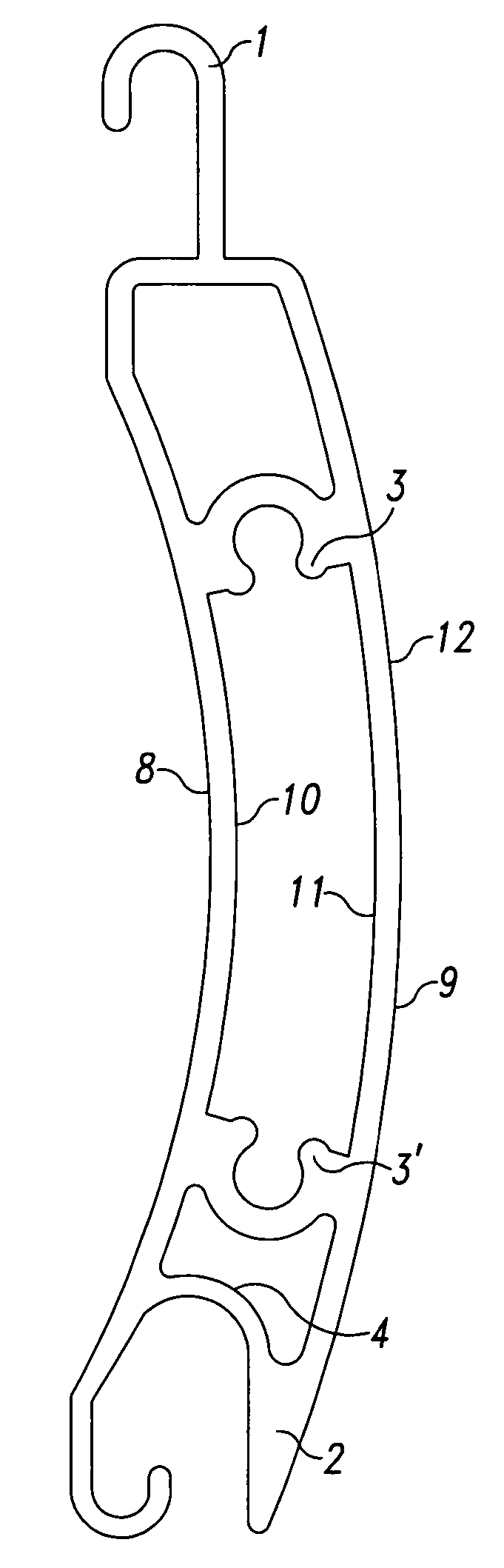
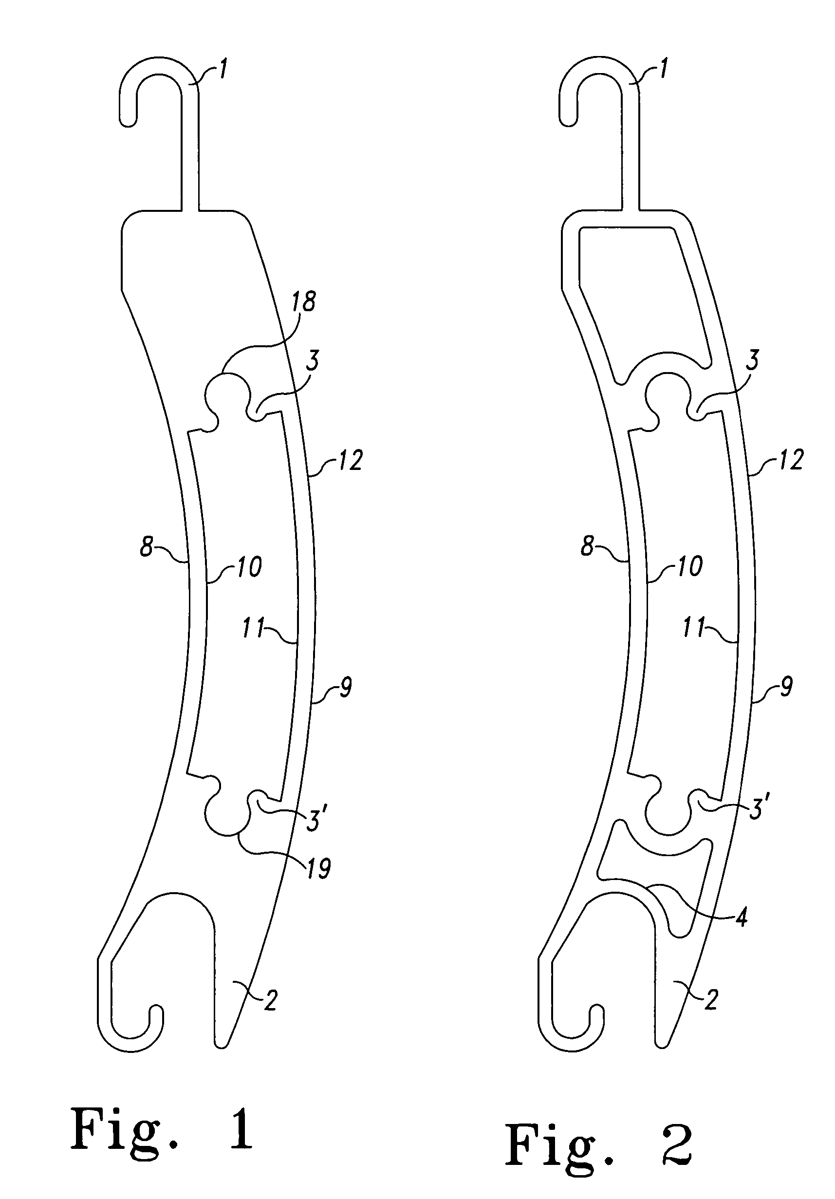
[0031]FIG. 1 illustrates the present invention, a side view of a dual boss shutter slat 12. According to the embodiment depicted in FIG. 1, shutter slat 12 is a generally hollow, elongated body of extruded aluminum having a first face 9 and a second face 8, and an upper edge 1 and a lower edge 2. The upper edge 1 comprises a track having a hook-shaped profile adapted to cooperate with the lower edge 2 of an identical slat, also comprising a track having a hook-shaped profile. The hollow interior of the slat is defined by the interior surfaces of the first and second faces, 11 and 10 respectively, and the interior surfaces of the upper and lower edges, 18 and 19 respectively. Shutter slat 12 also has a first end X and a second end Y, not shown in FIG. 1.

[0032]The shutter slat 12 shown in FIG. 1 further includes two bosses, 3 and 3′ which project into the generally hollow interior of the shutter slat 12 and run the length of the shutter slat 12, from the first end X to the second end ...

third embodiment

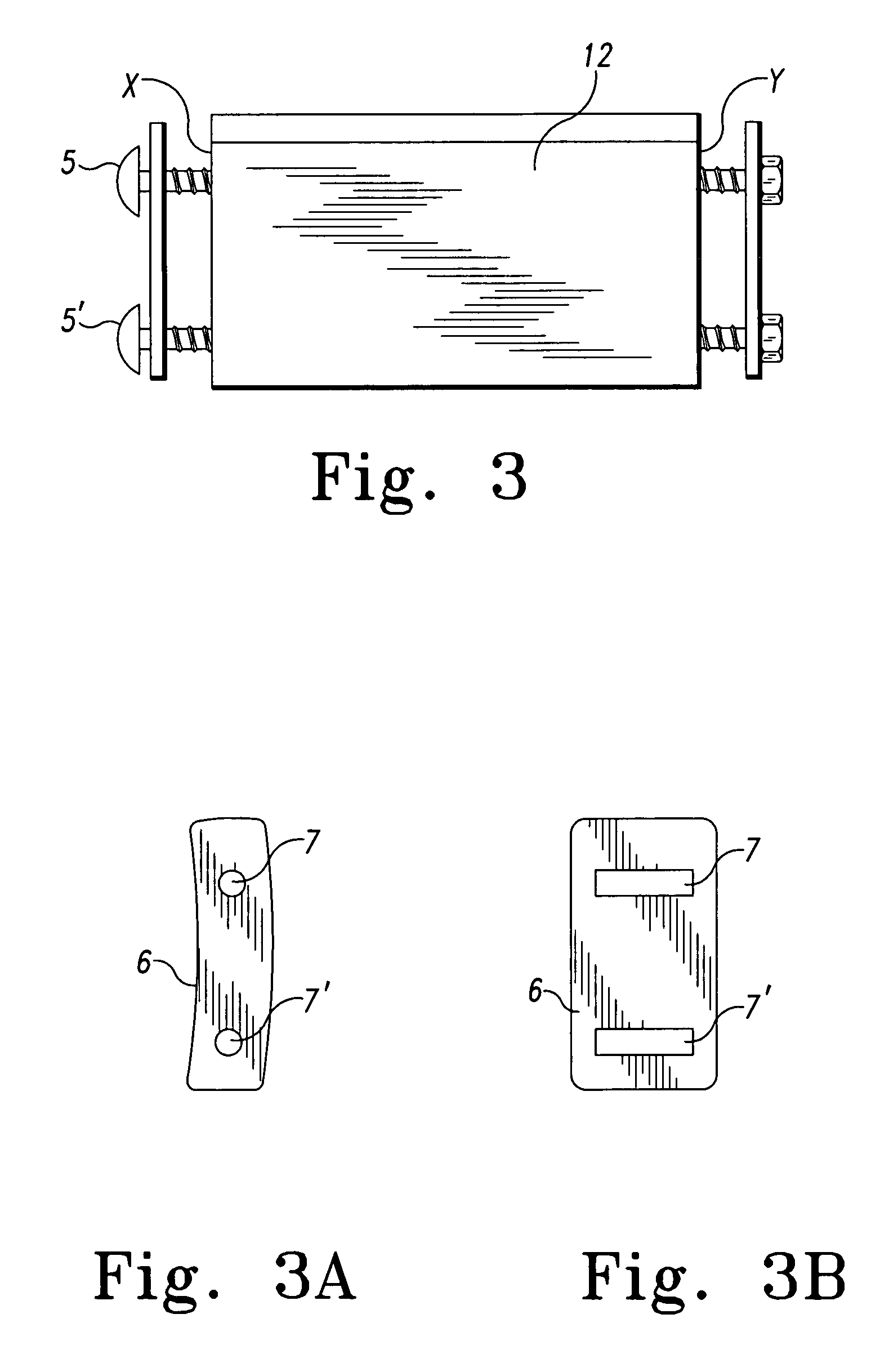
[0038]FIG. 3 illustrates a partial elevation of the present invention. Retention screws 5 and 5,′ engaged with bosses 3 and 3′ (not shown) are disposed at ends X and Y of shutter slat 12. According to a second aspect of the present invention, shutter slat 12 is further provided with a retention plate 6 located at end Y. One or more retention plates 6 may be used in conjunction with a shutter slat 12 and retention screws 5 and 5′. As shown in FIG. 3a, an elevation of retention plate 6, retention plate 6 is typically a flat plate having two apertures 7 and 7′ adapted to receive the retention screws 5 and 5′. Although a rectangular shape is shown, a retention plate 6 could have any number of shapes including round, oblong, oval, trapezoidal, or other geometric shape. In a particularly preferred embodiment, one retention plate 6 and one set of retention screws 5 and 5′ are used in combination with a first end X of the shutter slat 12, and a second retention plate 6 and set of retention ...


PUM


Abstract

A rolling shutter and a slat for use in a rolling shutter are provided. The slat comprises a first receptacle and a second receptacle, wherein each receptacle is c-shaped and adapted to receive a retention screw, and wherein each receptacle projects from one or more of interior surfaces of the shutter slat.

Description

BACKGROUND OF THE INVENTION[0001]1. Field of the Invention[0002]The present invention relates to shutters and in particular to shutters of the roller type having improved resistance to storms and break-ins. Furthermore, this invention relates to a shutter having improved retraction capability.[0003]2. Description of the Related Art[0004]Conventional roller shutters are designed to provide security from break-ins or protection from storms. The shutters must maintain appropriate structural integrity while extended in order to provide security and protection, but the design of a roller shutter must also allow a user to conveniently extend or retract the shutter on demand. Even though conventional roller shutters may need to be extended and retracted frequently or unexpectedly, such shutters have been prone to jam and / or snag. In addition, various factors influence the strength of a shutter and its ability to withstand forces of nature and attempts by intruders to break in through the a...

Claims


Application Information

Patent Timeline
Patent Type & Authority Patents(United States)
IPC IPC(8): E06B3/06E06B9/15E06B9/58
CPCE06B9/581E06B2009/1583
Inventor MILLER, JAMES V.
Owner QUALITAS MFG
Why Eureka
Try Eureka