Stoma plug

a technology of stoma and pouch, which is applied in the field of stoma pouches, can solve the problems of significant potential disadvantages, plugs described in u.s. pat. no, and an extremely embarrassing and belittling experience for many ostomates

Active Publication Date: 2007-08-21
CONVATEC TECH INC
View PDF14 Cites 30 Cited by
  • Summary
  • Abstract
  • Description
  • Claims
  • Application Information

AI Technical Summary

Benefits of technology

[0013] Such a structure may provide a simple, yet highly effective arrangement of chambers, without an undesirable long and / or rigid connection tube between the chambers.
[0015](e) The second chamber may be detachable from the device once the first chamber has been inflated. The second chamber may be re-attachable, or the detachment may be permanent (e.g. by breaking a frangible connection). A valve (e.g., the one-way valve mentioned above) may be provided for closing the first chamber to prevent escape of the inflation fluid from the first chamber.
[0035](i) A pressure relief valve that opens when pressure in the second chamber reaches a pre-set value, thereby preventing further inflation of the first chamber.
[0036](ii) A valve between the first and second chamber that closes when pressure in the second chamber exceeds a pre-set value, thereby preventing further inflation of the first chamber
[0037](iii) A valve between the first and second chamber that closes when pressure in the first chamber exceeds a pre-set value, thereby preventing further inflation of the first chamber

Problems solved by technology

However, the wearing of such a pouch can be an extremely embarrassing and belittling experience for many ostomates.
Although the idea of an inflatable plug is highly appealing in theory, the plug described in U.S. Pat. No. 4,950,223 has significant potential disadvantages.
The presence of such a relatively stiff tube inside the stoma may be undesirable in terms of safety for the ostomate.
Secondly, it is not possible to vent flatus while the bung is inflated in the stoma.
This presents severe limitations for the ostomate, because the ostomate will have to collapse the bung very frequently in order to avoid an uncomfortable accumulation of flatus within the body.
Finally, the design of the plug is very complicated and therefore expensive, and the sliding seal may be prone to leakage of fluid.
A leakage of fluid reduces the sealing pressure in the bung, and hence reduces the effectiveness of the plug.

Method used


Image

  • Stoma plug
  • Stoma plug
  • Stoma plug

Examples


Embodiment Construction

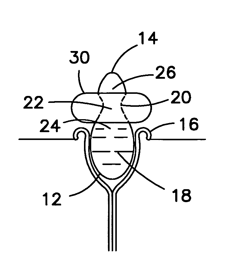
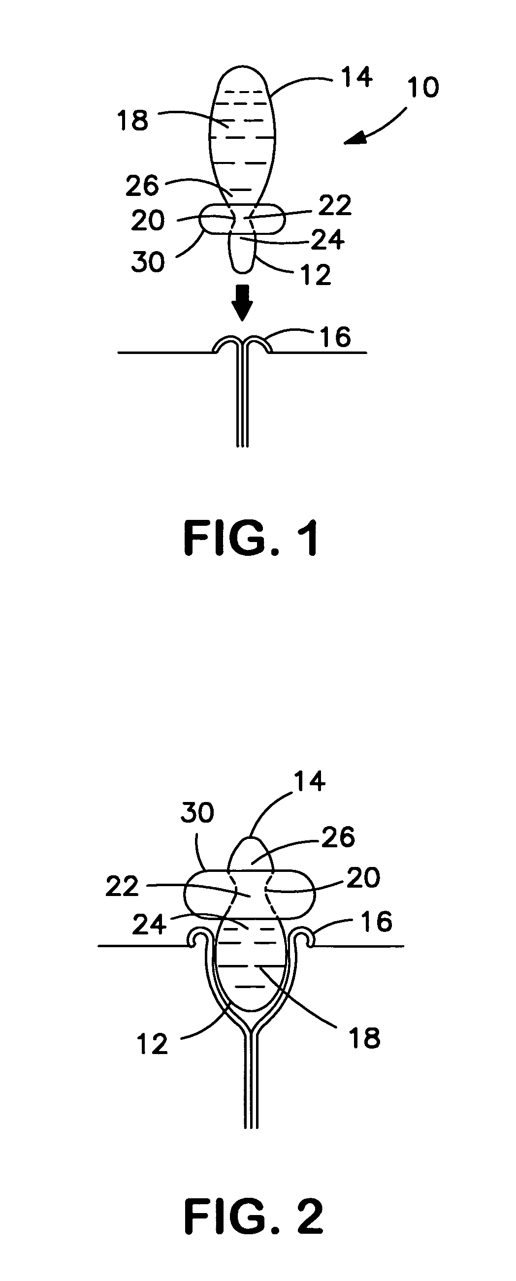
[0056]Referring to FIGS. 1 and 2, an ostomy plug 10 may be illustrated for at least partial insertion into a patient's stoma 16, for plugging the stoma 16. The ostomy plug 10 may be configured to obstruct the passage of solid and / or semi-solid and / or liquid body waste when the plug 10 is in a deployed condition. The ostomy plug 10 may be configured to allow venting of flatus through and / or around the plug 10 even in the deployed condition of the plug 10.

[0057]The plug 10 may comprise a first chamber 12 and a second chamber 14. The first chamber 12 may be in fluid communication with the second chamber 14. The first chamber 12 may be configured as an inflatable bung for at least partial insertion into the stoma 16. The second chamber 14 may be configured as an inflation driver for supplying fluid to inflate the first chamber 12. The first and second chambers 12 and 14 may together contain a predetermined amount of inflation fluid 18 which may be less than the combined maximum internal...


PUM


Abstract

An ostomy plug is described comprising first and second chambers having adjacent ends coupled to, and in fluid communication with, each other. The first chamber may be for insertion into a stoma. The second chamber may contain fluid for inflating the first chamber when the second chamber is squeezed or otherwise compressed. The plug may have a figure-of-eight configuration. The plug may be configured to permit venting of flatus while obstructing escape of other body waste from the stoma. The plug may incorporate an insertion aid for aiding insertion into a stoma. The plug may also incorporate a device for regulating the inflation pressure of the fluid to avoid undesirably high inflation pressures in the stoma.

Description

FIELD OF THE INVENTION[0001]The present invention may relate to the field of stoma plugs, for insertion at least partly into a patient's stoma for plugging the stoma. One aspect of the invention may relate to an inflatable stoma plug.BACKGROUND TO THE INVENTION[0002]The creation of an ostomy (stoma) is the therapy for many sufferers of diseases or injury of the gastrointestinal or urinary tract. An ostomy is the rerouting of the tract through the abdominal wall to outside the patient's body. Once a stoma has been created, the patient must, usually for the rest of his or her life, use a device worn on the body for capturing or containing the body waste. This has traditionally been done with a bag or pouch attached to the body with adhesive patches or constricting belts. However, the wearing of such a pouch can be an extremely embarrassing and belittling experience for many ostomates. A pouch requires significant changes in public and personal activities.[0003]A stoma plug offers the ...

Claims


Application Information

Patent Timeline
Patent Type & Authority Patents(United States)
IPC IPC(8): A61F2/02
CPCA61F5/445
Inventor DAVIES, GERAINTCLINE, JOHNGREGORY, CHRISTOPHER C.CUCKNELL, ALANSCARFE, JULIANCAUWOOD, PETE
Owner CONVATEC TECH INC
Why Eureka
Try Eureka