Locking assembly

a technology of locking mechanism and assembly, which is applied in the direction of carpet fasteners, light support devices, building scaffolds, etc., can solve the problems of known locking mechanism noise, ease of installation and dislodging such devices, and simplicity of design of known locking mechanism, so as to achieve little to no noise and minimal noise

Inactive Publication Date: 2007-08-28
CONTROL DYNAMICS
View PDF18 Cites 59 Cited by
  • Summary
  • Abstract
  • Description
  • Claims
  • Application Information

AI Technical Summary

Benefits of technology

[0006]The present invention is directed to a non-stored energy single motion locking assembly for attaching and locking a device to a surface that is easy to operate and has minimal moving parts that can break or fail.
[0008]The locking assembly further includes a yoke assembly having a yoke assembly plate that is of a size and shape to be received edgewise into the opening between the front and back plates via the top slot. A yoke is attached to the yoke assembly plate, with the yoke fixedly attached to a device that may be locked and mounted to the surface, as well as easily dislodged when desired.
[0010]To unlock and dislodge the yoke assembly plate (and, ergo, the device) from the bracket assembly (and surface), a force is applied to the upper leg of the pivoting release lever via the outer surface of the pivoting release lever. The pivoting release lever moves the lower leg upward to apply a dislodging force onto the lower edge of the yoke assembly plate. Thus, the yoke assembly and device are unlocked from the bracket assembly and may be readily removed from the bracket assembly (and the surface).
[0013]Another feature of the present invention is that the locking assembly is substantially noiseless in use. The pivoting action of the pivoting release lever makes minimal noise such that the present invention is particularly applicable for tactical (e.g., military) maneuvers in which attaching and detaching a device to a belt or vest with little to no noise is highly desired.

Problems solved by technology

Moreover, known locking mechanisms do not have simplicity of design and ease in installation and dislodging such a device, yet provide sufficient locking capabilities for joining a variety of devices to a solid surface.
Furthermore, known locking mechanisms make audible noise when locked or latched, which may be problematic for particular applications, such as those involving military or other tactical maneuvers.

Method used


Image

  • Locking assembly
  • Locking assembly
  • Locking assembly

Examples


first embodiment

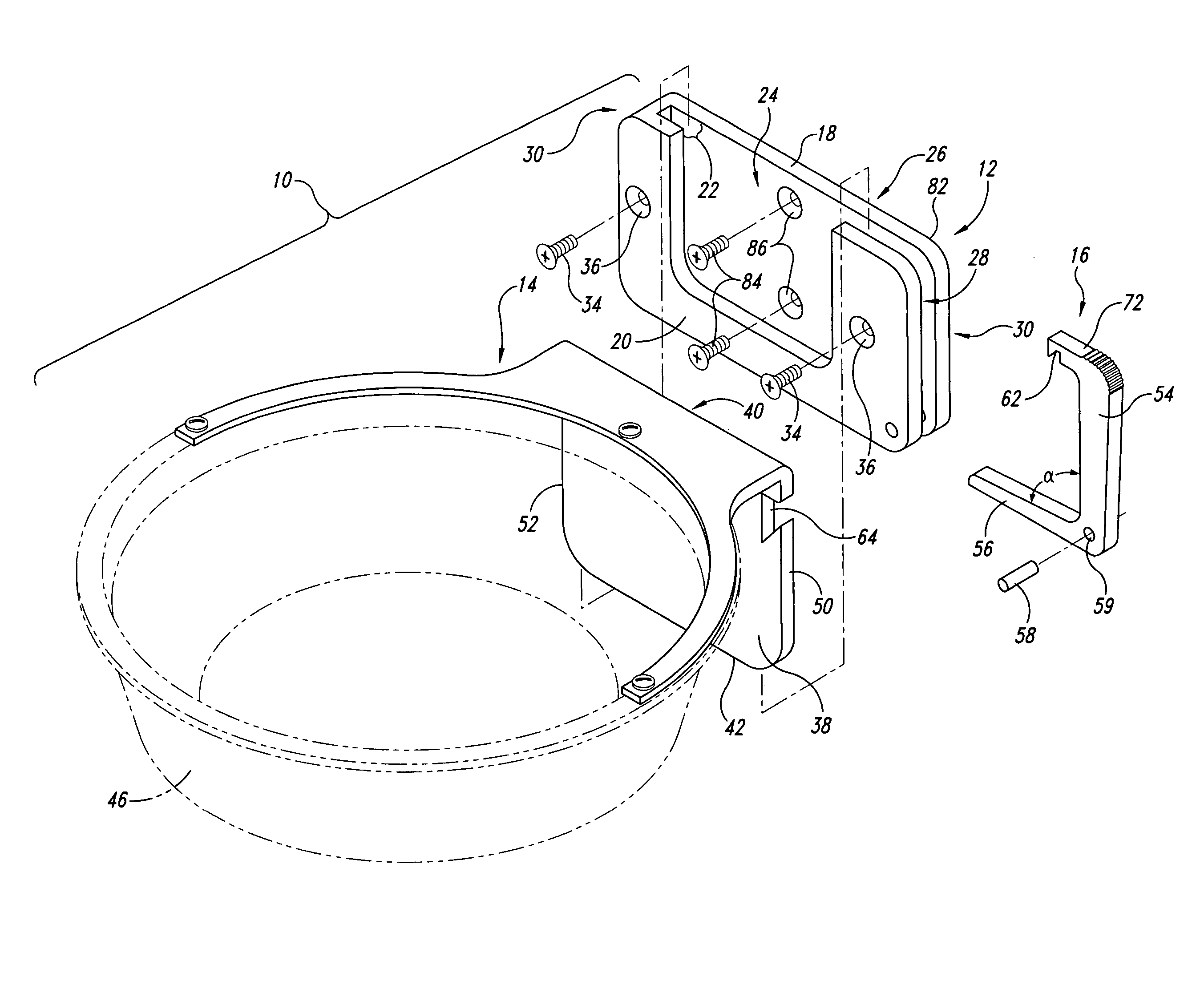
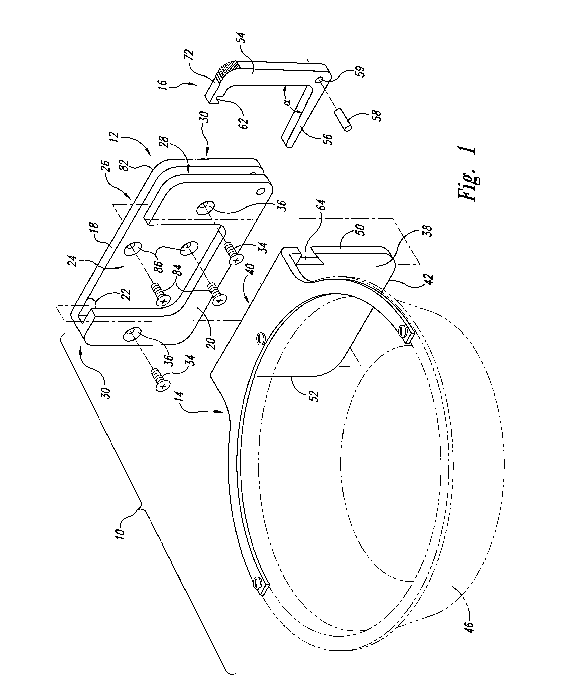
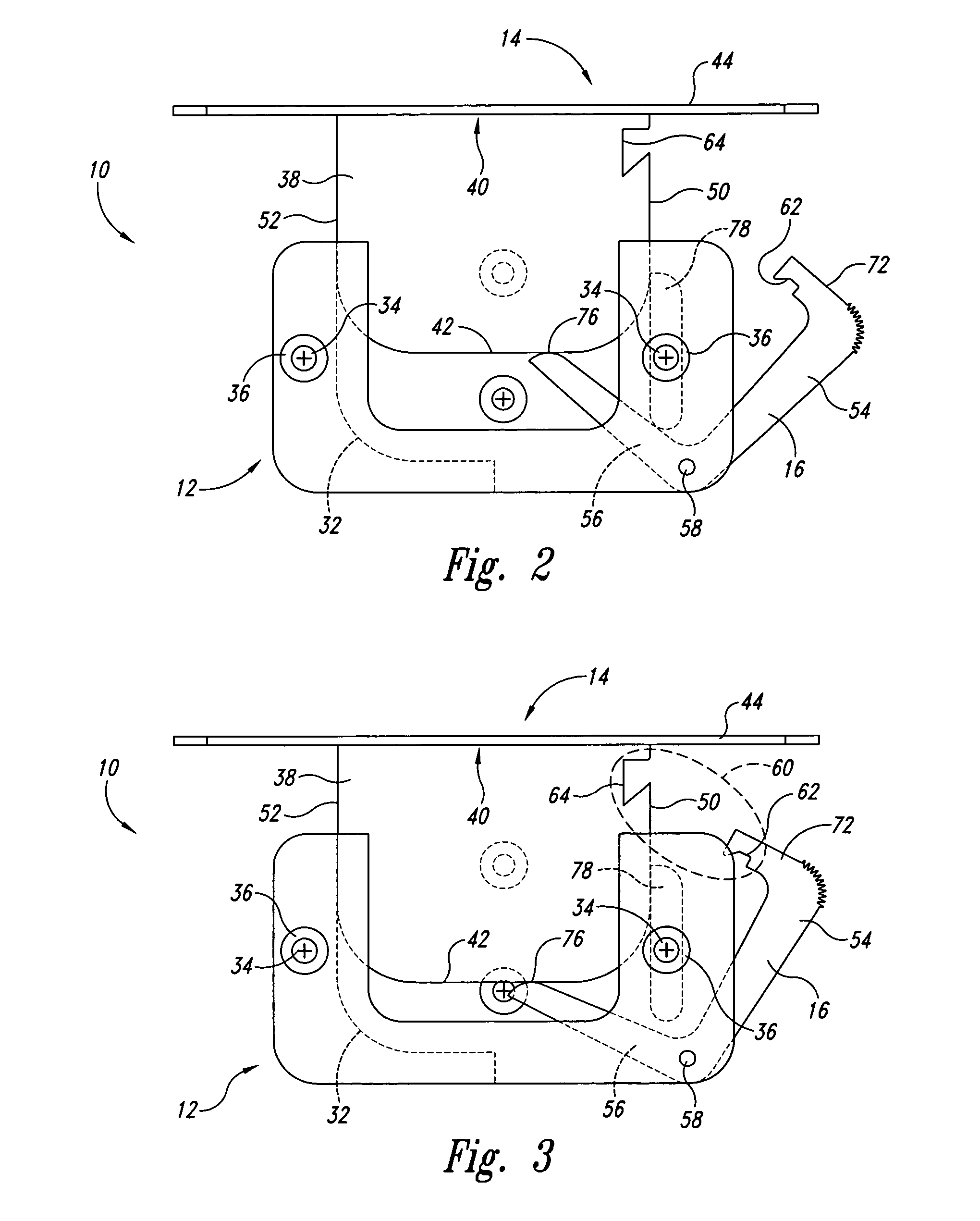
[0054]Referring to FIGS. 1-7, the locking assembly 10 of the first embodiment includes a bracket assembly 12, and a corresponding yoke assembly 14, and a pivoting release lever 16, that, when assembled, allows quick secure fixation and locking of the yoke assembly to the bracket assembly through a single motion locking movement of the pivoting release lever. Similarly, dislodgement of the device and yoke assembly can be equally easily obtained through the reverse action via the pivoting release lever.

[0055]The bracket assembly may be formed of a substantially rectangular back plate 18 and a substantially conforming mostly rectangular front plate 20 that are conjoined and spaced apart in such a way as to form a substantially continuous opening 22 between back plate 18 and front plate 20. Opening 22 forms a top slot 24 at the top 26 of bracket assembly 12 and at least one side slot 28 on either or both sides 30 of the bracket assembly.

[0056]The front and back plates are joined togethe...

second embodiment

[0075]Referring now to FIGS. 12-22, the invention 10′ includes a tamper resistant pivoting release lever 16′ in which a tamper-resistant barrel 88 (FIGS. 13-14) and locking mechanism 90 are added (FIG. 12, FIGS. 19-22).

[0076]Barrel 88, which is illustrated in a cylindrical shape, is of a shape to conform to a corresponding external key 92 (FIG. 15). Barrel 88 includes top end 92 and bottom end 94. At the bottom end 94 is a flange 96 that is moved within a slot 98 between a locked and unlocked position. In one embodiment, the flange 96 includes its own flanged ends 100 and slot 98 includes a spacer 102 along most of the arc-like path that the flange 96 travels within the slot. The exception is that at one end 104 of slot 98, a rotational force is applied to flange 96 in order to dislodge the flange 96 from a space 106 to which the spacer does not extend (where the flange 96 is unlocked relative to space 106 in slot 98 and allows rotational movement of the pivoting release lever 16′ w...


PUM


Abstract

A locking assembly for readily attaching and detaching a device to a surface such as a wall, non-planar surface, or a plurality of bars such as those found in a kennel. The locking assembly has a bracket assembly with a front and back plate that are fixedly attached to each other about portions of peripheries of the front and back plates defining an opening therebetween with a top slot and at least one side slot. The back plate is directly or indirectly fixedly attached to a surface. Positioned within at least one side slot is at least one pivoting release lever having an upper leg and lower leg movable about a pivot. The locking assembly further includes a yoke assembly having a yoke assembly plate of a size and shape to fit edgewise and be guided into the opening between the front and bottom plates via the top slot. The upper leg of the pivoting release lever and an exterior surface of the yoke assembly plate can be mateably restrained through a pair of interlocking notches. A yoke extending from and fixedly attached to the yoke assembly plate is attached to the device.

Description

RELATED APPLICATION[0001]The present application is a continuation-in-part of U.S. patent application Ser. No. 10 / 996,551 (Eric M. Moran, sole-inventor), filed Nov. 23, 2004 now U.S. Pat No. 7,077,372, and entitled “Locking Assembly For Mounting a Device to a Solid Surface.”TECHNICAL FIELD[0002]The present invention relates generally to locking mechanisms or assemblies. In particular, the present invention relates to a locking assembly with a pivoting release lever for mounting a device to a surface.BACKGROUND OF THE INVENTION[0003]Notwithstanding the co-pending application to which the present application claims priority, known locking mechanisms for mounting a device to a surface include convoluted mechanisms that have stored energy springs or do not lock the device sufficiently to the surface. One such sliding latch is illustrated in the Nelson 1400 Dog Feeding Pan, in which a dog pan is attached to a vertical surface (e.g., a wall). The sliding latch does not lock the device to ...

Claims


Application Information

Patent Timeline
Patent Type & Authority Patents(United States)
IPC IPC(8): A47B96/00
CPCA01K1/0356A45F5/02A47G7/044F16B2/10F16M11/041F16M13/02F21V21/02F21V21/0885F41C33/006F41C33/04G09F7/18G09F17/00A47G1/1606A01K5/0114Y10T24/4501A45F5/021A45F2200/0566Y10S292/29Y10T24/45089Y10T292/1037Y10T292/1043Y10T292/1063Y10T292/1069Y10T292/107Y10T292/1072Y10T292/696
Inventor MORAN, ERIC M.
Owner CONTROL DYNAMICS
Why Eureka
Try Eureka