Door catch

a door catch and door technology, applied in the field of door catch, can solve the problem of requiring a relatively high manufacturing cost, and achieve the effect of convenient assembly and mounting of the door catch

Inactive Publication Date: 2007-09-04
HSU MING PIAO
View PDF8 Cites 16 Cited by
  • Summary
  • Abstract
  • Description
  • Claims
  • Application Information

AI Technical Summary

Benefits of technology

[0003]A primary object of the present invention is to provide an improved door catch that omits the troublesome screws to enable easier assembling and mounting of the door catch.
[0004]Another object of the present invention is to provide an improved door catch that may be made of a plastic material instead of a metal material to thereby reduce the manufacturing cost of the door catch.
[0005]To achieve the above and other objects, the door catch of the present invention includes a back plate having two laterally symmetric sleeves formed on a front face thereof. An elastic check member is conveniently mounted in a rear end of each sleeve to replace a conventional screw to confine a steel ball and a spring in the sleeve, so that the spring normally pushes the steel ball forward to partially project from a front open end of the sleeve and the elastic check member backward to firmly close the rear end of the sleeve without the risk of moving out of the sleeve.

Problems solved by technology

Moreover, the conventional door catch with the above structure must be made of a metal material, and therefore requires a relatively high manufacturing cost.

Method used


Image

  • Door catch
  • Door catch

Examples


Embodiment Construction

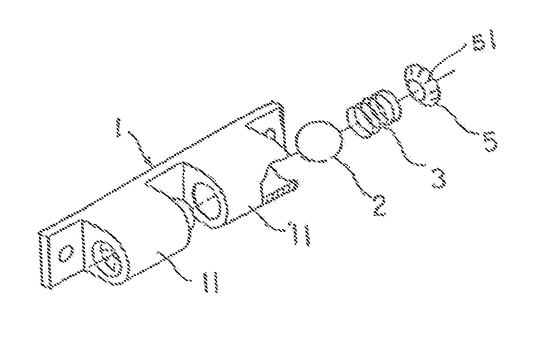
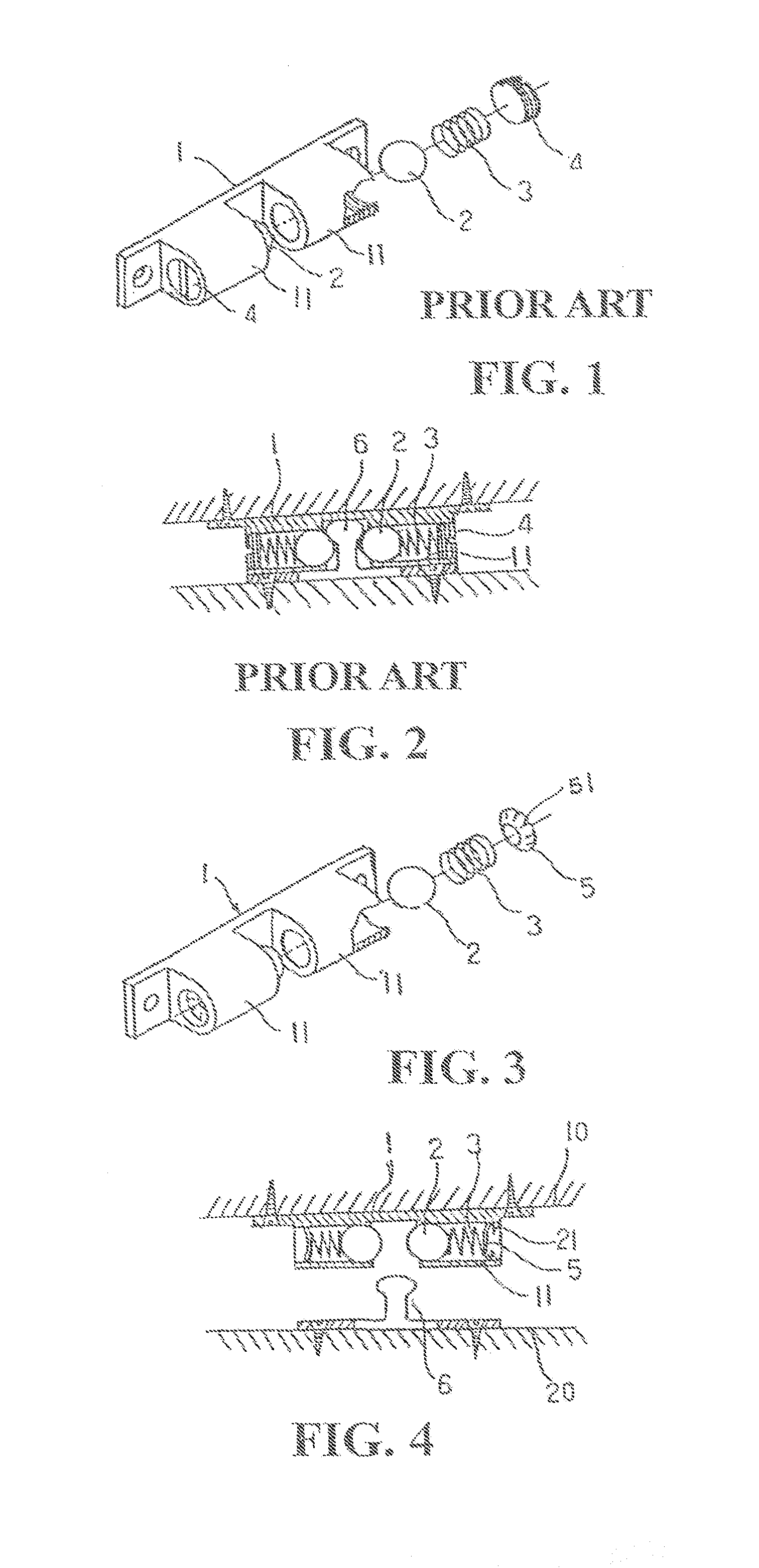
[0012]Please refer to FIGS. 3 and 4, which are exploded perspective view and assembled sectioned top view, respectively, of a door catch according to the present invention. As shown, the door catch of the present invention includes a back plate 1 having two laterally symmetric sleeves 11 formed on a front face thereof. A steel ball 2 and a spring 3 are sequentially mounted in each of the two sleeves 11. The door catch of the present invention is characterized in that an elastic check member 5 is mounted in a rear end of each of the sleeves 11 to be held in place immediately behind the spring 3, so that the spring 3 on the one hand elastically pushes the steel ball 2 forward to partially project from a front open end of the sleeve 11, and on the other hand elastically pushes the elastic check member 5 backward to firmly press against a rear end of the sleeve 11 without the risk of moving out of the sleeve 11.

[0013]According to a preferred embodiment of the present invention, the elas...


PUM


Abstract

A door catch includes a back plate having two laterally symmetric sleeves formed on a front face thereof. An elastic check member is mounted in a rear end of each sleeve to replace a conventional screw to confine a steel ball and a spring in the sleeve, so that the spring normally pushes the steel ball forward to partially project from a front open end of the sleeve and the elastic check member backward to firmly close the rear end of the sleeve. The steel balls projected from the two sleeves of the back plate together firmly clamp between them a stop post correspondingly mounted on a movable door leaf.

Description

FIELD OF THE INVENTION[0001]The present invention relates to a door catch, and more particularly to a door catch that includes two elastic check members to enable easier assembling and mounting as well as reduced manufacturing cost of the door catch.BACKGROUND OF THE INVENTION[0002]In a conventional door catch as shown in FIGS. 1 and 2, there is included a back plate 1 having two laterally symmetric sleeves 11 formed on a front face thereof. A steel ball 2 and a spring 3 are sequentially mounted in each of the two sleeves 11, and a screw 4 is screwed to a rear end of the sleeve 11 to confine the ball 2 and the spring 3 in the sleeve 11, so that the ball 2 is normally pushed by the spring 3 to partially project from a front open end of the sleeve 11. To use the door catch, first fixedly mount the back plate 1 on a wall 10 with fastening elements to correspond to a stop post 6 fixedly mounted on a back of a movable door leaf 20, so that the stop post 6 is clamped by and between the tw...

Claims


Application Information

Patent Timeline
Patent Type & Authority Patents(United States)
IPC IPC(8): E05C19/00
CPCE05C19/04Y10S292/15Y10T16/625Y10T16/61Y10T16/615Y10T292/0808Y10T292/14
Inventor HSU, MING-PIAO
Owner HSU MING PIAO
Why Eureka
Try Eureka