High speed connectors that minimize signal skew and crosstalk

a high-speed connector and crosstalk technology, applied in the direction of coupling device connection, coupling device details, coupling protective earth/shielding arrangement, etc., can solve the problems of signal integrity degradation, signal skew, signal integrity degradation, etc., to minimize crosstalk, minimize intermingling electrical fields, and maximize the effect of connector signal density

Active Publication Date: 2007-10-16
FCI AMERICAS TECH LLC
View PDF15 Cites 59 Cited by
  • Summary
  • Abstract
  • Description
  • Claims
  • Application Information

AI Technical Summary

Benefits of technology

[0009]An electrical connector is disclosed, comprising, in one embodiment, a first and a second contact with a third contact at an angle to and electrically connecting the first and second contacts, wherein an electrical path through the first, second, and third contacts is a first transmission path, and a fourth and a fifth contact with a sixth contact at an angle to and electrically connecting the fourth and fifth contacts, wherein the electrical path through the fourth, fifth, and sixth contacts is a second transmission path, and wherein the first and second transmission paths have a relatively similar signal propagation time. Contacts may be placed in grooves carved out of a metal core associated with electrical ground to minimize intermingling electrical fields between conductors and thus minimize cross talk and maximize signal density of the connector.

Problems solved by technology

In many applications of electrical connectors, for example electrical connectors associated with printed wiring boards (PWB), the physical characteristics and close proximity of the signal contacts within the electrical connector may cause degradation of signal integrity.
Degradation of signal integrity may be caused by signal propagation delay in one conductor with regard to a related conducted.
Signal propagation delay is commonly referred to as “signal skew” or “skew.” One cause of skew in an electrical connector is varying electrical paths within the connector through which signals are conducted.
The unequal signal propagation time causes signal skew and degrades signal integrity.
Another cause of signal degradation is commonly called “crosstalk.” Crosstalk occurs when one signal contact induces electrical interference in another signal contact that is in proximity to it.
The electrical interference is caused by intermingling electrical fields between the two contacts.
Such interference is a particular problem when signal contacts are closely spaced in electrical connectors.
Like skew, crosstalk also may cause significant degradation of signal integrity.
Minimizing skew by decreasing contact spacing, however, may create or further intensify crosstalk.
The solution to crosstalk, therefore, may create or intensify skew and decrease the signal density of the electrical connector.

Method used


Image

  • High speed connectors that minimize signal skew and crosstalk
  • High speed connectors that minimize signal skew and crosstalk
  • High speed connectors that minimize signal skew and crosstalk

Examples


Embodiment Construction

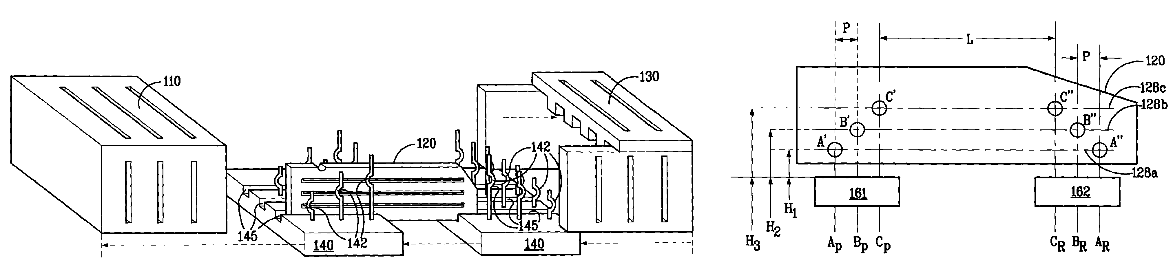
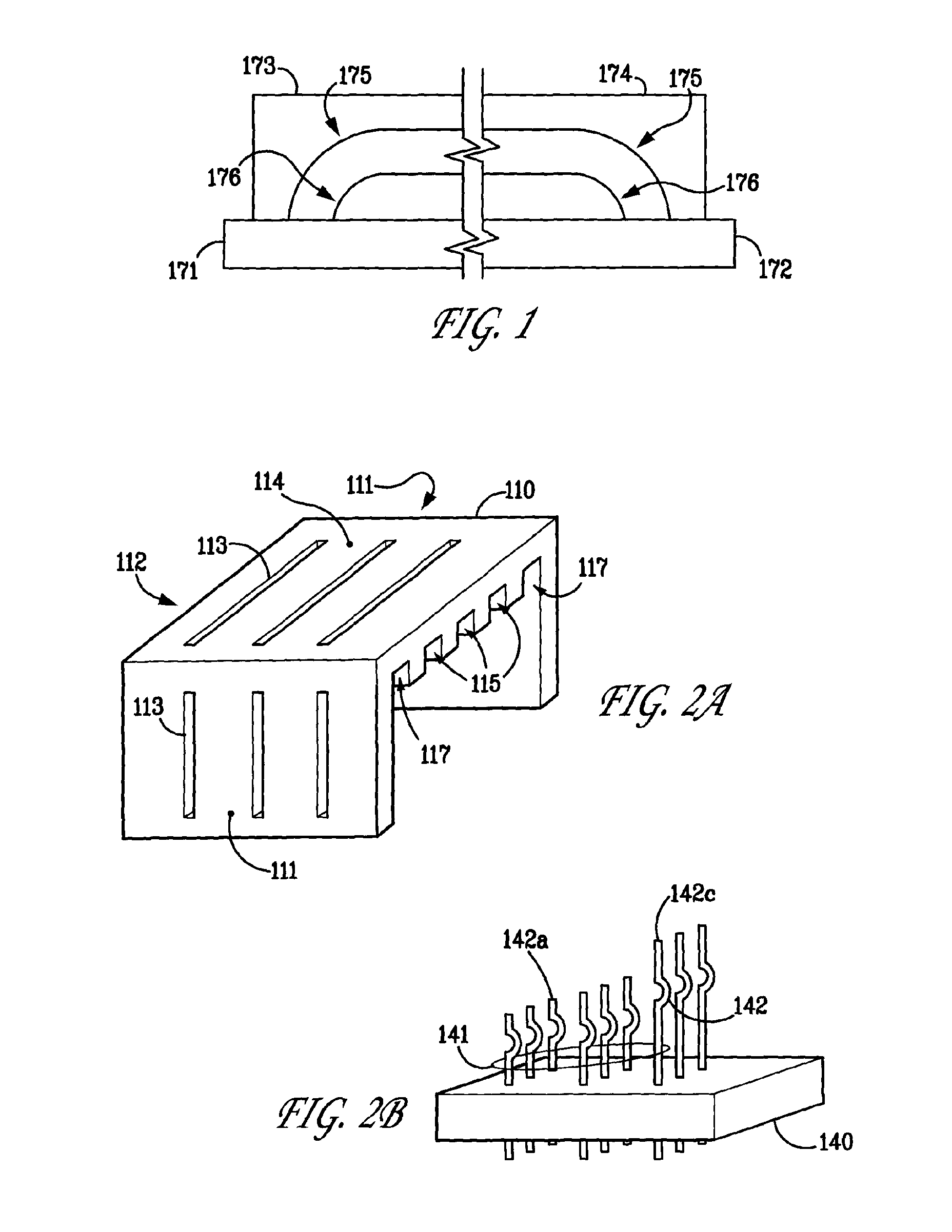
[0027]FIG. 2A depicts an example embodiment of a plug housing 110. Plug housing 110 includes side walls 111, a rear wall 112, and a ceiling 114. Plug housing 110 may contain contact plate slots 115 adapted to receive contact plates (not shown). Plug housing 110 may also comprise receptacle housing slots 117 for receiving and facilitating connection with a receptacle housing by allowing the sides of the receptacle housing to slide into the receptacle housing slots 117 of plug housing 110. Plug housing 110 also may include air slits 113 on ceiling 114 or side walls 111 to facilitate thermal release and improve the thermal properties of the electrical connector. Plug housing 110 is shown to be configured to receive three contact plates (not shown) in slots 115 and to receive the receptacle housing sides in receptacle housing slots 117. Plug housing 110, however, may be adapted to receive any number of contact plates. Additionally, a receptacle housing (not shown) may be connected to pl...


PUM


Abstract

The invention is an electrical connector that minimizes signal skew caused by varying propagation times through different transmission paths within the connector, minimizes crosstalk caused by intermingling electric fields between signal contacts, and maximizes signal density within the connector. The electrical connector may include a plug and receptacle housing, plug contacts, receptacle contacts, and contact plates. The contact plates may include connecting contacts that electrically connect plug contacts to receptacle contacts. The electrical connector minimizes signal skew by maintaining substantially equal-length transmission paths within the connector through varying the lengths and positions of plug and receptacle contacts. The electrical connector minimizes crosstalk by surrounding the connecting contacts with electrical ground by placing the connecting contacts in grooves of the connecting plates. Placing the contacts in such grooves maximizes the signal density of the contact by enabling the contacts to be placed in close proximity with other contacts while minimizing crosstalk.

Description

FIELD OF THE INVENTION[0001]Generally, the invention relates to electrical connectors. More particularly, the invention relates to electrical connectors that provide high speed, uniform signal propagation, and low interference communications.BACKGROUND OF THE INVENTION[0002]Electrical connectors provide signal connections between electronic devices using signal contacts. In many applications of electrical connectors, for example electrical connectors associated with printed wiring boards (PWB), the physical characteristics and close proximity of the signal contacts within the electrical connector may cause degradation of signal integrity. Two causes of signal degradation in electrical connectors are commonly referred to as “skew” and “crosstalk.”[0003]Degradation of signal integrity may be caused by signal propagation delay in one conductor with regard to a related conducted. Signal propagation delay is commonly referred to as “signal skew” or “skew.” One cause of skew in an electri...

Claims


Application Information

Patent Timeline
Patent Type & Authority Patents(United States)
IPC IPC(8): H01R13/648
CPCH01R13/6477H01R13/6471H01R12/716
Inventor BELOPOLSKY, YAKOV
Owner FCI AMERICAS TECH LLC
Why Eureka
Try Eureka