Hermetically sealed flashlight assembly

a flashlight and seal technology, applied in the field of sealable flashlight assemblies, can solve the problems of prone to leakage, wear and tear of seals, and the assembly is watertight, and achieves the effect of high intensity light and sufficient durability

Active Publication Date: 2007-10-30
EMISSIVE ENERGY A DELAWARE
View PDF9 Cites 33 Cited by
  • Summary
  • Abstract
  • Description
  • Claims
  • Application Information

AI Technical Summary

Benefits of technology

[0008]Further, the flashlight of the present invention includes a novel modular interface arrangement that allows the flashlight to be interfaced with a variety of different equipment or reconfigured in order to facilitate use for different functionality such as a marker light, a runway indicator light or a weapon mounted light.
[0009]It is therefore an object of the present invention to provide a flashlight that has an operational range that exceeds the operational limits encountered with prior art flashlights. It is a further object of the present invention to provide a flashlight that has a hermetically sealed interior and which eliminates substantially all of the air from the interior of the flashlight while also preventing the entry of moisture thereinto. It is yet a further object of the present invention to provide a flashlight that can be actuated using interior and exterior components that do not require a physical interface thereby eliminating a weak point in the housing. It is still a further object of the present invention to provide a sealed flashlight that can serve a variety of different functional needs and provide an ability to interface the flashlight with a broad range of other equipment and accessories.

Problems solved by technology

Typically, in prior art flashlights manufactured for use underwater, one of the major problems is making the assembly watertight.
Waterproofing the operable components of the switch tends to be particularly troublesome.
After prolonged use, these seals wear and are prone to leakage.
Other parts, such as removable ends for replacement of battery and bulb, also must be sealed and servicing the unit often results in damage to or destruction of the seals.
Further, if these flashlights are configured for use in deep water at depths approaching 350 feet below sea level, they typically require a pressure-equalizing valve to prevent them from imploding from the force of the surrounding environmental pressures.
This problem is further complicated when the same light is also required to operate at high altitudes such as at 35,000 feet above sea level.
Generally, the pressure-equalizing device used for underwater applications will fail at high altitudes and the high altitude device will fail in deep water.
These pressure equalization issues are exacerbated by the fact that the portable flashlights in the prior art typically include a cylindrical housing that encloses the light source, power source, required circuitry, the operable switch element and a relatively large volume of air.
Further, the slide type switch or a spring loaded button type switch of these prior art flashlights require that a portion of the operable components reside on the exterior of the light while another portion is positioned on the interior resulting in a weak point at the interface between these operable elements.

Method used


Image

  • Hermetically sealed flashlight assembly
  • Hermetically sealed flashlight assembly
  • Hermetically sealed flashlight assembly

Examples


Embodiment Construction

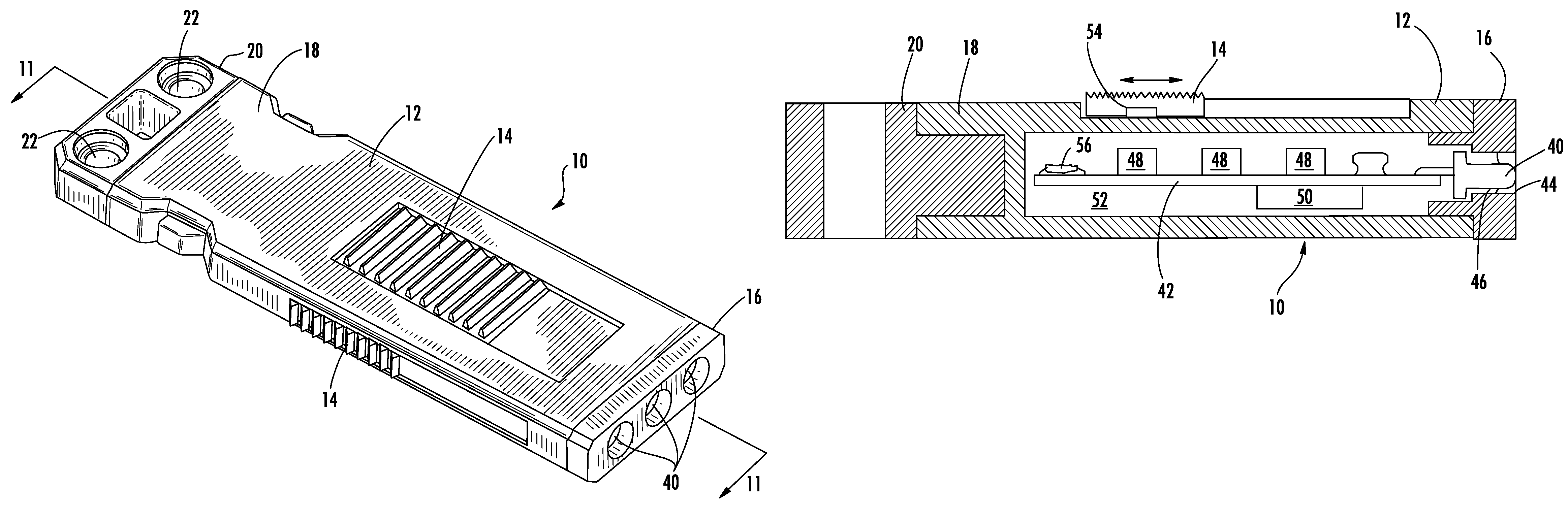
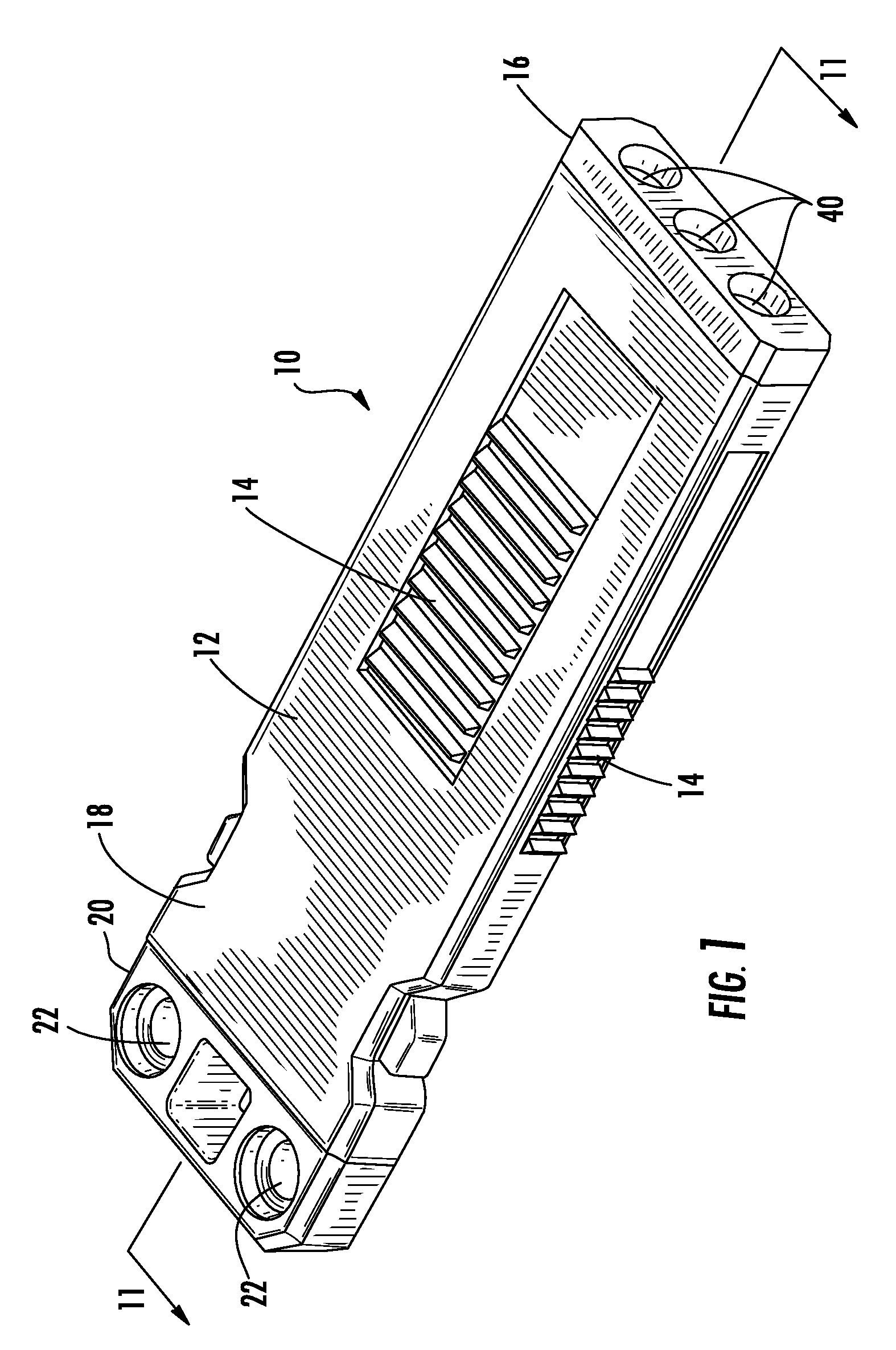
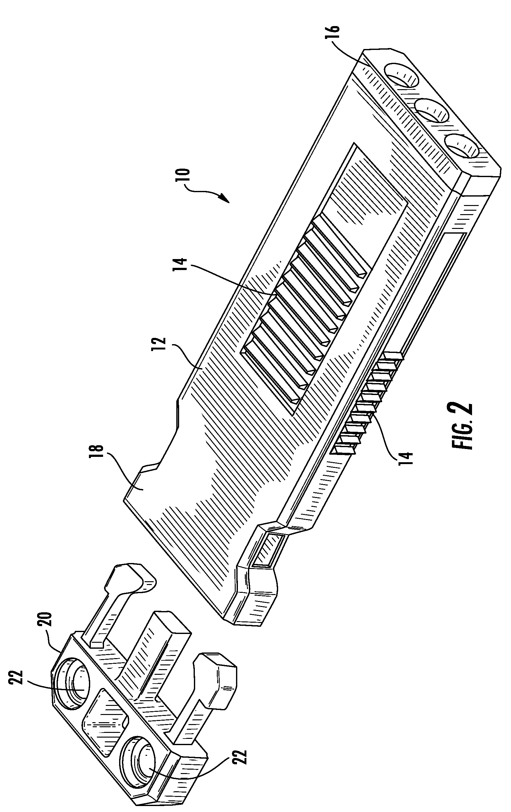
[0023]Now referring to the drawings, the lighting assembly of the present invention is shown and generally illustrated in the figures as 10. The lighting assembly 10 is the central component for the modular system described herein. The lighting assembly 10 can be seen to include an outer housing 12, at least one slide switch 14, a head assembly 16 and a modular interface 18 for receiving various modular accessories including the modular accessory mount 20 shown.

[0024]The outer housing 12 of the lighting assembly 10 of the present invention is configured in a novel manner to allow its integration into various systems and configurations. The outer housing 12 is formed to include a modular interface 18 that serves as one end of a detachable clip element. As can best be seen in FIG. 2, the modular interface 18 is shown as being formed as a female receptor end of a detachable clip assembly. Similarly, although not shown, the modular interface 18 provided on the housing 12 of the lighting...


PUM


Abstract

A lighting assembly that incorporates a high brightness LED in a compact assembly that is sealed and sufficiently durable for a continuous operational range of between 350 feet below sea level and 35,000 feet above sea level. Further, the flashlight of the present invention includes a novel modular interface arrangement that allows the flashlight to be interfaced with a variety of different equipment or reconfigured in order to facilitate use for different functionality such as a marker light, a runway indicator light or a weapon mounted light.

Description

CROSS-REFERENCE TO RELATED APPLICATIONS[0001]This application is related to and claims priority from earlier filed U.S. Provisional Patent Application No. 60 / 557,234, filed Mar. 29, 2004.BACKGROUND OF THE INVENTION[0002]The present invention relates generally to a sealed flashlight assembly. More specifically, the present invention relates to a new portable flashlight assembly and more particularly to compact flashlight assembly that is highly durable and completely sealed against the effects of environmental pressure changes while also being constructed for easy mounting and integration into a variety of applications.[0003]Typically, in prior art flashlights manufactured for use underwater, one of the major problems is making the assembly watertight. Waterproofing the operable components of the switch tends to be particularly troublesome. Often rubber diaphragms and covers have been used as outer seals and the switch must be operated through the seal. After prolonged use, these sea...

Claims


Application Information

Patent Timeline
Patent Type & Authority Patents(United States)
IPC IPC(8): F21L4/00F21L2/00F21L4/02F21V23/04F21V31/04
CPCF21L4/027F21V21/0824F21V23/0414F21V31/04Y10T24/45581F21Y2101/02Y10T24/3408Y10T24/3407F21Y2115/10
Inventor GALLI, ROBERT D.
Owner EMISSIVE ENERGY A DELAWARE
Why Eureka
Try Eureka