Master station in communications system and access control method

a communication system and access control technology, applied in the field of master stations in communications systems and access control methods, can solve problems such as interference in another communication system, drastic drop in signal intensity, and devices in the system may become unable to communicate with other devices, so as to achieve the effect of avoiding interferen

Active Publication Date: 2008-03-18
PANASONIC CORP
View PDF5 Cites 37 Cited by
  • Summary
  • Abstract
  • Description
  • Claims
  • Application Information

AI Technical Summary

Benefits of technology

[0009]Therefore, an object of the present invention is to provide a master station and an access control method which, in the presence of a plurality of communications systems sharing the same channel, easily avoids interferences between the communications systems while guaranteeing QoS in the communication bands of the communications systems, without having to perform transmission power control.
[0017]Thus, according to the present invention, the communication band is divided into a beacon period, a guaranteed-band period (TDMA or FDMA), and a CSMA period, and the allocation in the TDMA or FDMA period is determined based on the information of the communication band used by each communications system. As a result, even in the case where plural communications systems share the same channel, it is possible to easily avoid interferences between communications systems without having to perform transmission power control, while retaining good QoS in the communication bands for the respective communications systems.

Problems solved by technology

However, in the case where the above-described communications system is a power line communications system, due to the characteristics of the power line transmission path, signal attenuation within a device's own communications system may far exceed the signal attenuation which causes interference in another communications system, depending on the configuration of the devices which are connected to the network.
In other words, in the case where the technique of Japanese Laid-Open Patent Publication No. 2002-198834 or Japanese Laid-Open Patent Publication No. 2003-37556 is applied to a power line communications system, if interference between communications systems is prevented through power control, some of the devices in the system may become unable to perform communications with other devices due to a reduced signal intensity, depending on the device configuration.
In the case of a wireless communication, too, a similar phenomenon may occur in that an attenuation in the signal intensity due to shielding obstacles may cause a drastic drop in the signal intensity despite a small physical distance.
With such conventional structures, it is impossible, through transmission power control, to suppress interferences for other communications systems while maintaining a good communication quality within a device's own communications system.
Therefore, there has been a problem in that the throughput in each communications system is greatly deteriorated due to interferences between the communications systems, and that it is difficult to control the communication band.

Method used


Image

  • Master station in communications system and access control method
  • Master station in communications system and access control method
  • Master station in communications system and access control method

Examples


first embodiment

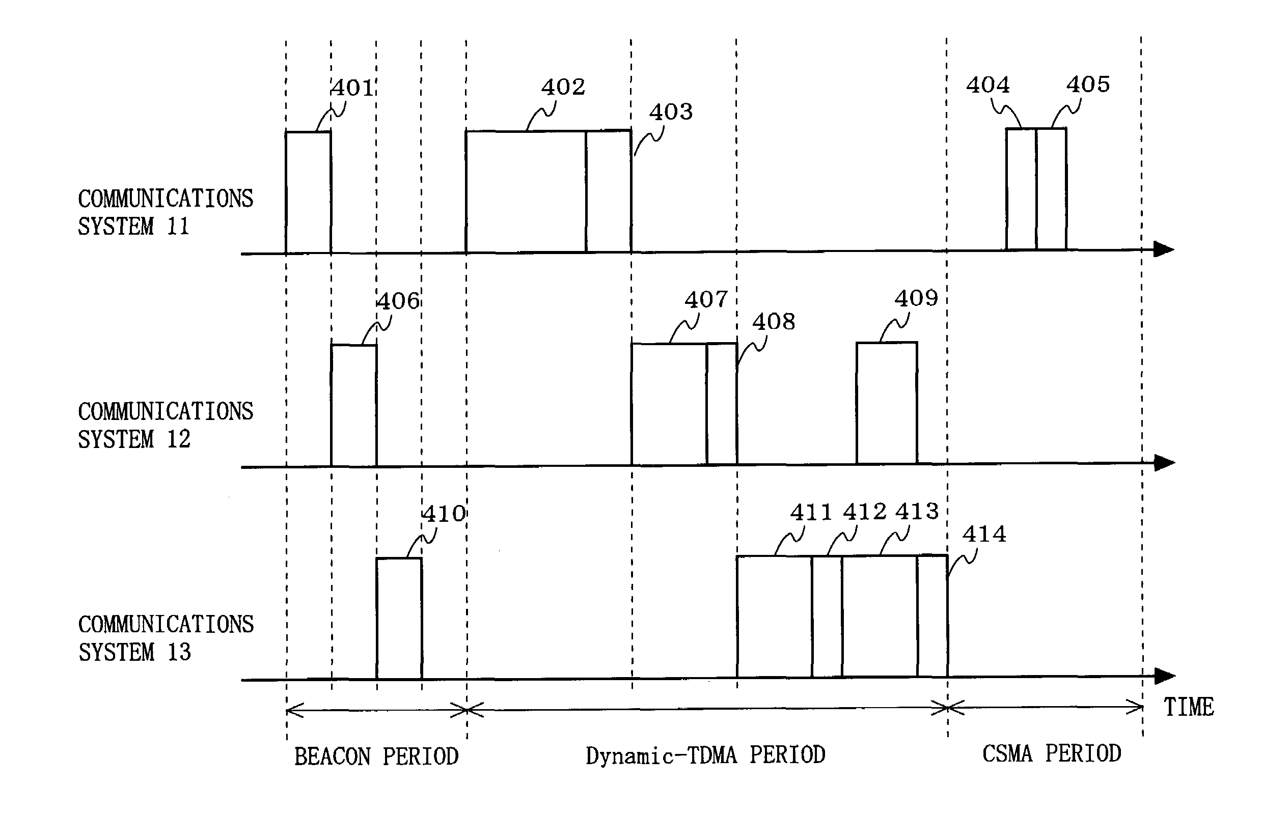
[0034]FIG. 4 is a timing diagram illustrating an access control method according to a first embodiment of the present invention. In the access control method according to the first embodiment, the communication band is divided into a beacon period, a TDMA period in which a communication band (communication slot) to be used is dynamically allocated through time division (hereinafter this period will be referred to as a “Dynamic-TDMA period”), and a CSMA (Carrier Sense Multiple Access) period. The ratio between Dynamic-TDMA period and the CSMA period does not need to be constant. The ratio may dynamically vary depending on the total communication bandwidth required by a particular station which is permitted to perform communications in the Dynamic-TDMA period.

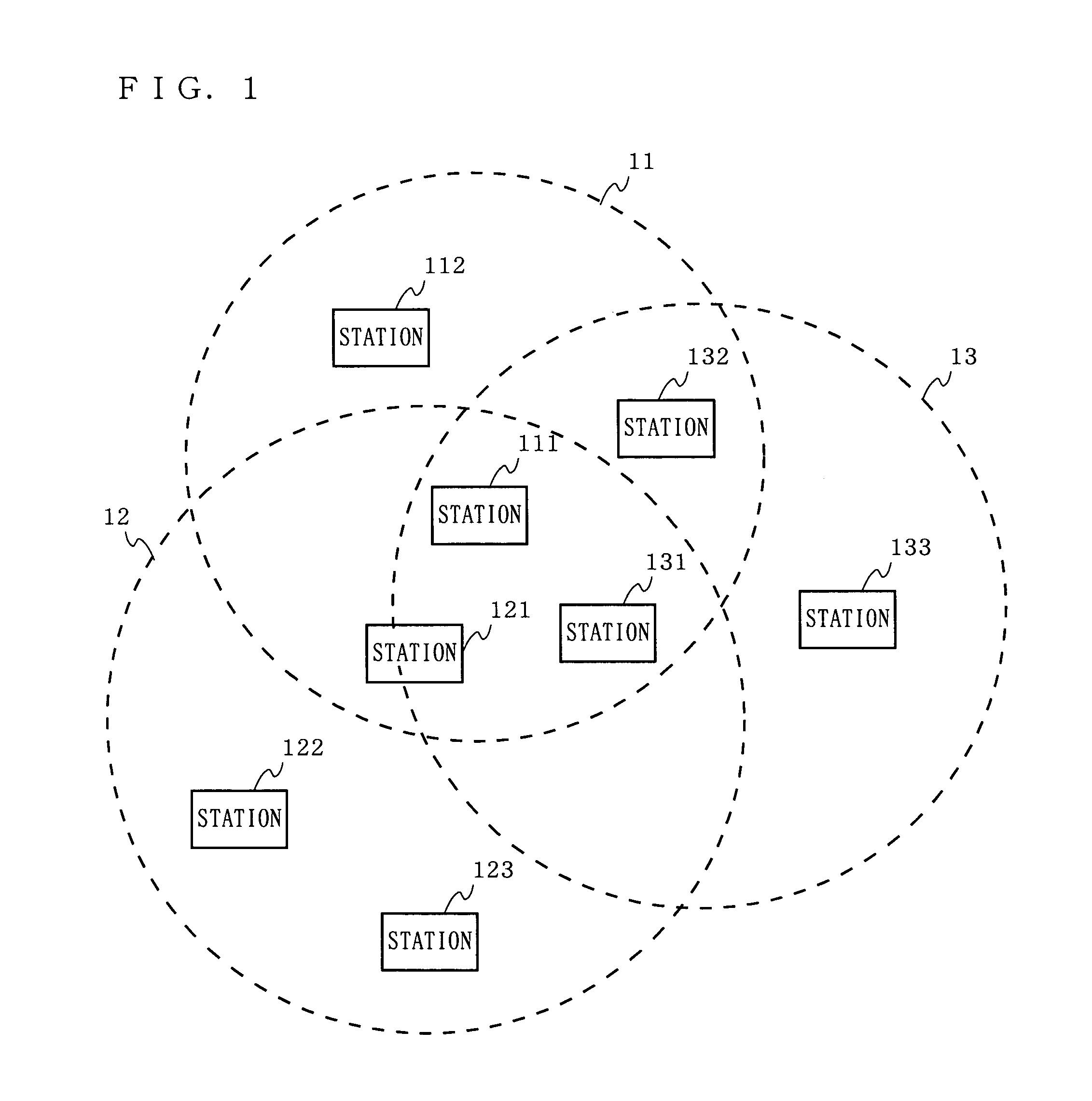
[0035]When a start time of the beacon period is reached, each of the master stations 111, 121 and 131 transmits its own beacon packet, in a previously allocated transmission slot. In the example shown in FIG. 4, the master statio...

second embodiment

[0051]FIG. 8 is a timing diagram illustrating an access control method according to a second embodiment of the present invention. In the access control method according to the second embodiment, the communication band is divided into a beacon period, an FDMA period in which a communication band to be used is dynamically allocated through frequency division (hereinafter this period will be referred to as a “Dynamic-FDMA period”), and a CSMA period.

[0052]When a start time of the beacon period is reached, each of the master stations 111, 121 and 131 transmits its own beacon packet, in a previously allocated transmission slot. In the example shown in FIG. 8, the master stations 111, 121 and 131 of the communications systems 11, 12 and13 respectively transmit beacon packets 801, 806 and 810 in this order. In each beacon packet, a transmission time for the beacon packet, a start time of the beacon period, a start time of the Dynamic-FDMA period, a start time of the CSMA period, etc., as g...


PUM


Abstract

A communication band is divided into: a beacon period in which every master station transmits a beacon packet in competition with one another; a guaranteed-band period (e.g., a TDMA period or an FDMA period) in which only a specific permitted station is allowed access; and a CSMA period in which every station is allowed access in competition with one another. Plural master stations exchange information of a communication band used in the guaranteed-band period with each other, and based on the respective information, a communication band available to the master station's own communications system in the guaranteed-band period is calculated.

Description

BACKGROUND OF THE INVENTION[0001]1. Field of the Invention[0002]The present invention relates to a master station to be used in a communications system and an access control method. More particularly, the present invention relates to an access control method which is to be used by a plurality of communications system sharing the same channel and which prevents interferences between the communications systems.[0003]2. Description of the Background Art[0004]As a technique for reducing interferences occurring between a plurality of communications system sharing the same channel, access control methods for reducing the influences of interference waves by using transmission power control have been proposed, as disclosed in, e.g., Japanese Laid-Open Patent Publication No. 2002-198834 and Japanese Laid-Open Patent Publication No. 2003-37556.[0005]Japanese Laid-Open Patent Publication No. 2002-198834 discloses a method where an attenuator is provided in a base station for attenuating signal...

Claims


Application Information

Patent Timeline
Patent Type & Authority Patents(United States)
IPC IPC(8): H04L12/413H04B7/00H04W16/14H04W48/08H04W72/00H04W72/04H04W74/02H04W74/08H04W84/12H04W84/20
CPCH04W72/00H04W28/04H04W48/08H04W84/20H04W72/04H04W74/08
Inventor YOSHIZAWA, KENSUKEOHMI, SHINICHIROYAMAGUCHI, TSUYOSHI
Owner PANASONIC CORP
Why Eureka
Try Eureka