Power slips

a technology of power slips and slip plates, applied in the field of power slips, can solve the problem that the strength of the collar is normally insufficient, and achieve the effect of reducing the strength of the collar

Inactive Publication Date: 2010-03-23
NABORS DRILLING TECH USA INC
View PDF14 Cites 28 Cited by
  • Summary
  • Abstract
  • Description
  • Claims
  • Application Information

AI Technical Summary

Problems solved by technology

The collar normally has insufficient strength to bear the weight of a lengthy string of casing, thus the slips have to be configured to grip the exterior of the casing below the collar.

Method used


Image

  • Power slips
  • Power slips
  • Power slips

Examples


Embodiment Construction

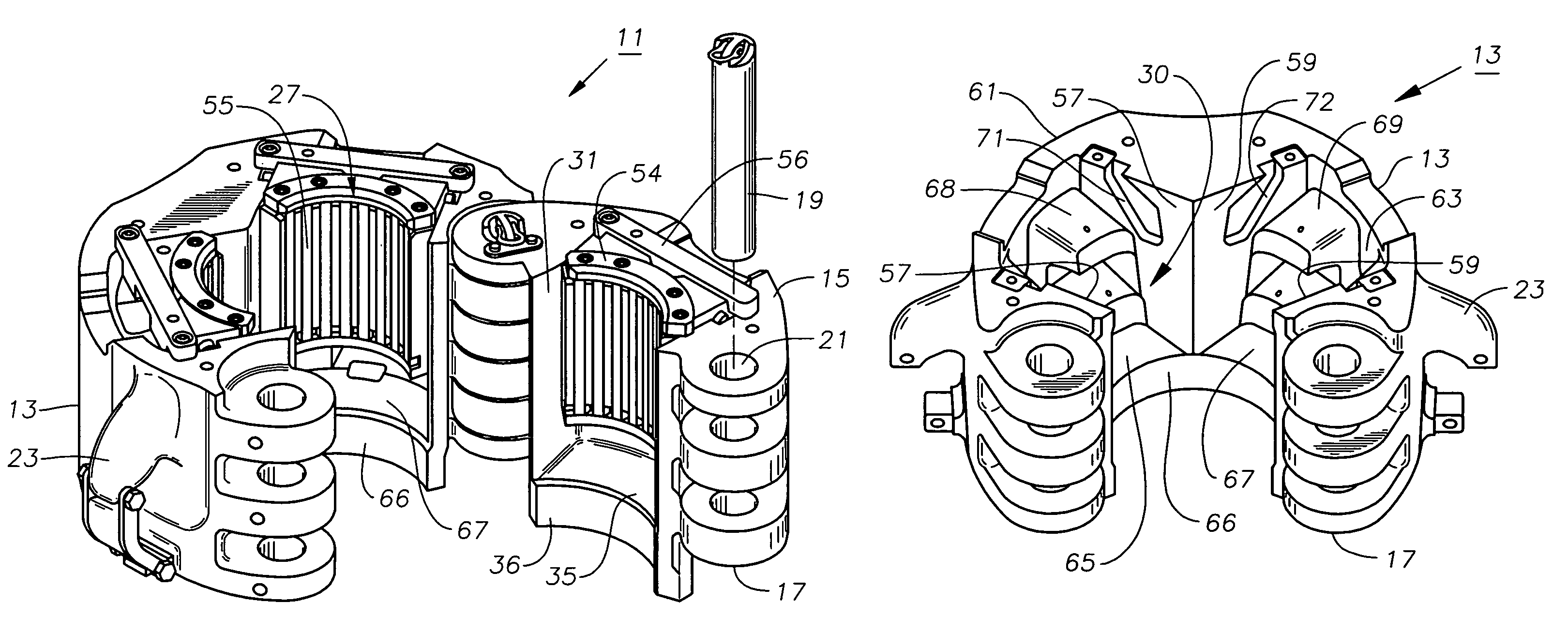
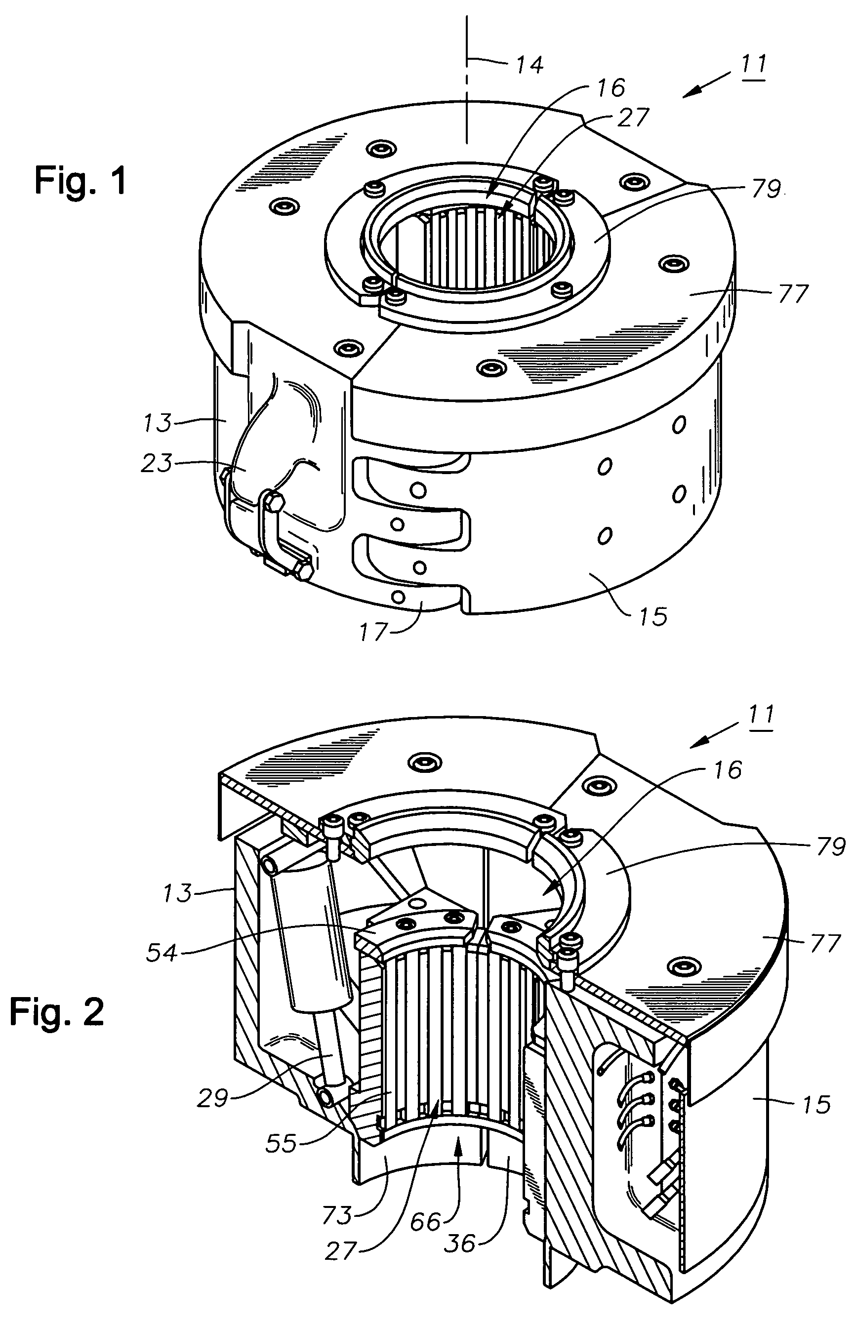
[0025]Referring to FIG. 1, power slips 11 has a housing made up of a larger housing segment 13 that is secured to a smaller housing segment 15 by hinge plates 17. Housing segments 13, 15 define a cylindrical member with a hole 16 extending therethrough along an axis 14. Larger housing segment 13 extends circumferentially a greater amount around axis 14 than smaller housing segment 15. In this example, larger housing segment extends about 240 degrees around axis 14, and smaller housing segment 15 extends about 120 degrees.

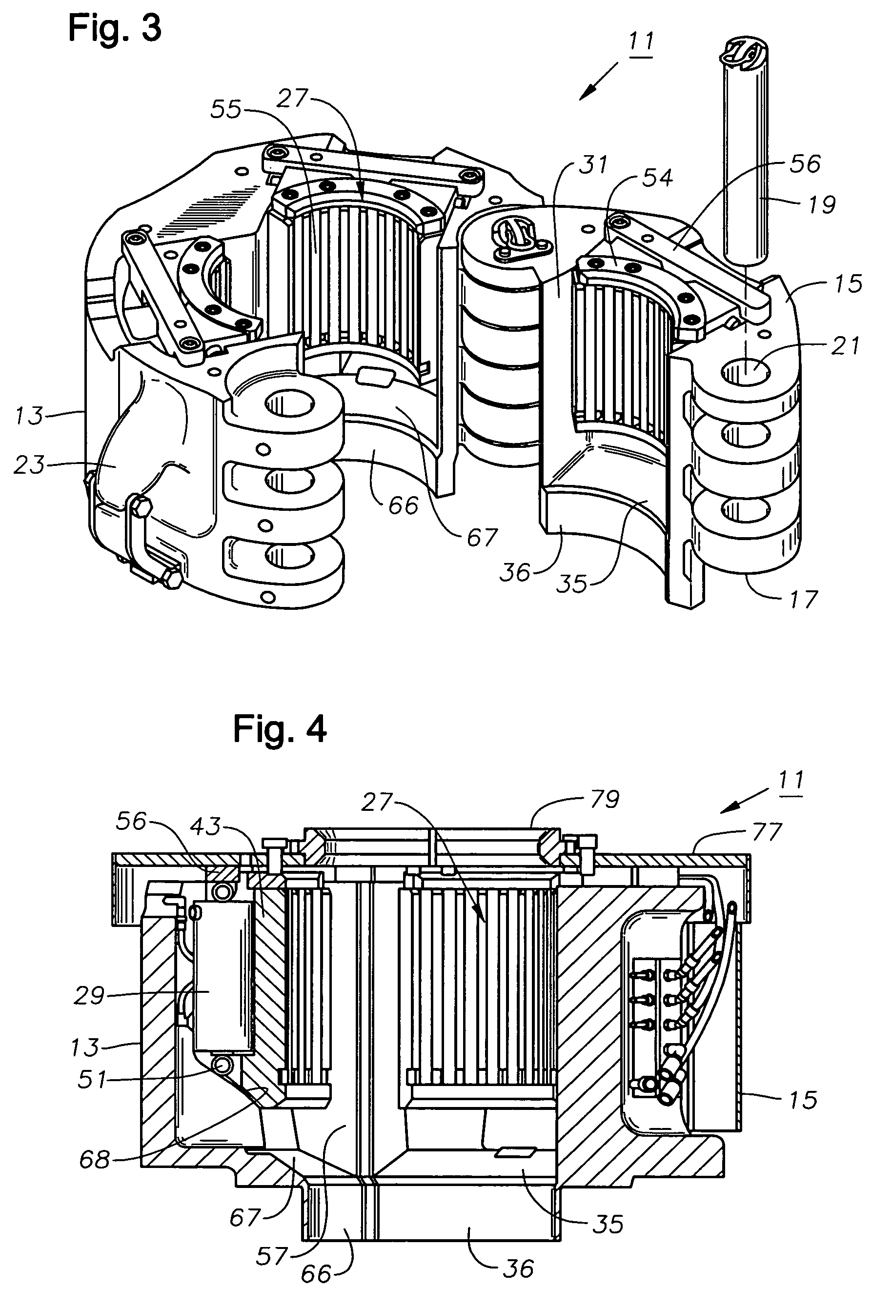
[0026]As shown also in FIG. 3, each hinge plate 17 is engaged by a pin 19 extending through mating holes 21. Referring again to FIG. 1, in this embodiment, power slips 11 also has a pair of lugs 23 spaced on opposite sides. Lugs 23 are used to connect power slips 11 to elevator bails 25 (FIG. 15) when power slips 11 is used as an elevator.

[0027]Referring to FIG. 2, power slips 11 holds a plurality of slip segments 27. In this embodiment, there are three slip segment...


PUM


Abstract

A slip assembly for gripping pipe during well drilling operations has a housing with a hole for receiving a section of pipe. Pockets in the housing are spaced circumferentially around the hole. Each of the pockets has side walls that face toward each other and are connected to each other by a back wall that has at least one ramp surface. A slip segment is located in each pocket, each slip segment having side edges that engage the side walls of one of the pockets. Each slip segment has a back side with a ramp surface that engages the ramp surface on the back wall of the pocket. Each of the slip segments is movable within its pocket from an upper outward position to a lower inward position in gripping engagement with the pipe.

Description

FIELD OF THE INVENTION[0001]This invention relates in general to power slips used to support pipe during oil and gas well drilling operations.BACKGROUND OF THE INVENTION[0002]During oil and gas well drilling, at certain depths and at total depth, the operator typically runs and cements a string of casing in the well. The string of casing is made up of sections of pipe, each about 40 feet in length. Each section of pipe has externally threaded ends, one of which has a collar secured to it, the collar having internal threads.[0003]While picking up another section of casing, the operator supports the made-up string of casing in the well with slips at the rig floor. The collar normally has insufficient strength to bear the weight of a lengthy string of casing, thus the slips have to be configured to grip the exterior of the casing below the collar.[0004]Generally the slips comprise a plurality of segments that slide up and down a conical bowl between released and gripping positions. Pow...

Claims


Application Information

Patent Timeline
Patent Type & Authority Patents(United States)
IPC IPC(8): E21B19/07
CPCE21B19/06E21B19/10E21B19/07
Inventor CEROVSEK, MILAN
Owner NABORS DRILLING TECH USA INC
Why Eureka
Try Eureka