Vehicle suspension system

a chassis system and vehicle technology, applied in the direction of deflectable wheel steering, bicycles, transportation and packaging, etc., can solve the problems of not being able to connect the engine and drive train, the tilt of the drive system, and the angle of all components of the chassis, so as to improve the fuel economy, smooth the ride, and the suspension is so

Active Publication Date: 2010-05-25
DIEZIGER HELEN IRENE
View PDF26 Cites 56 Cited by
  • Summary
  • Abstract
  • Description
  • Claims
  • Application Information

AI Technical Summary

Benefits of technology

[0013]In view of the above-mentioned unfulfilled needs, the present invention embodies, but is not limited by, the following objects and advantages:
[0015]A second objective is to provide improved fuel economy over non-tilting chassis systems.
[0016]A third objective is to provide a softer suspension and a smoother ride as compared to a two-wheel chassis system.
[0017]A fourth objective is to provide better traction and breaking control as compared to a two-wheel chassis system.
[0020]A seventh objective is to simplify by eliminating sensors and feedback systems having the purpose of controlling the lean angle of a tilting chassis.

Problems solved by technology

Such a tilt of the drive system, however, would not be compatible with an engine and drive train connected to driven wheels through a differential, as might be desirable for the reasons discussed above.
If the differential were to be tiltable, the rotation of the drive shaft would bias the tilt attitude while creating complex angles with the driven axles.
This may be an over-complication, however, considering the case of a motorcycle where no control other than that provided by the rider is needed.
All components of Moulene's chassis, however, also tilt.
Moulene does not disclose sufficient detail of the drive mechanism to understand how it would operate in the context of a tilt.

Method used


Image

  • Vehicle suspension system
  • Vehicle suspension system
  • Vehicle suspension system

Examples


Embodiment Construction

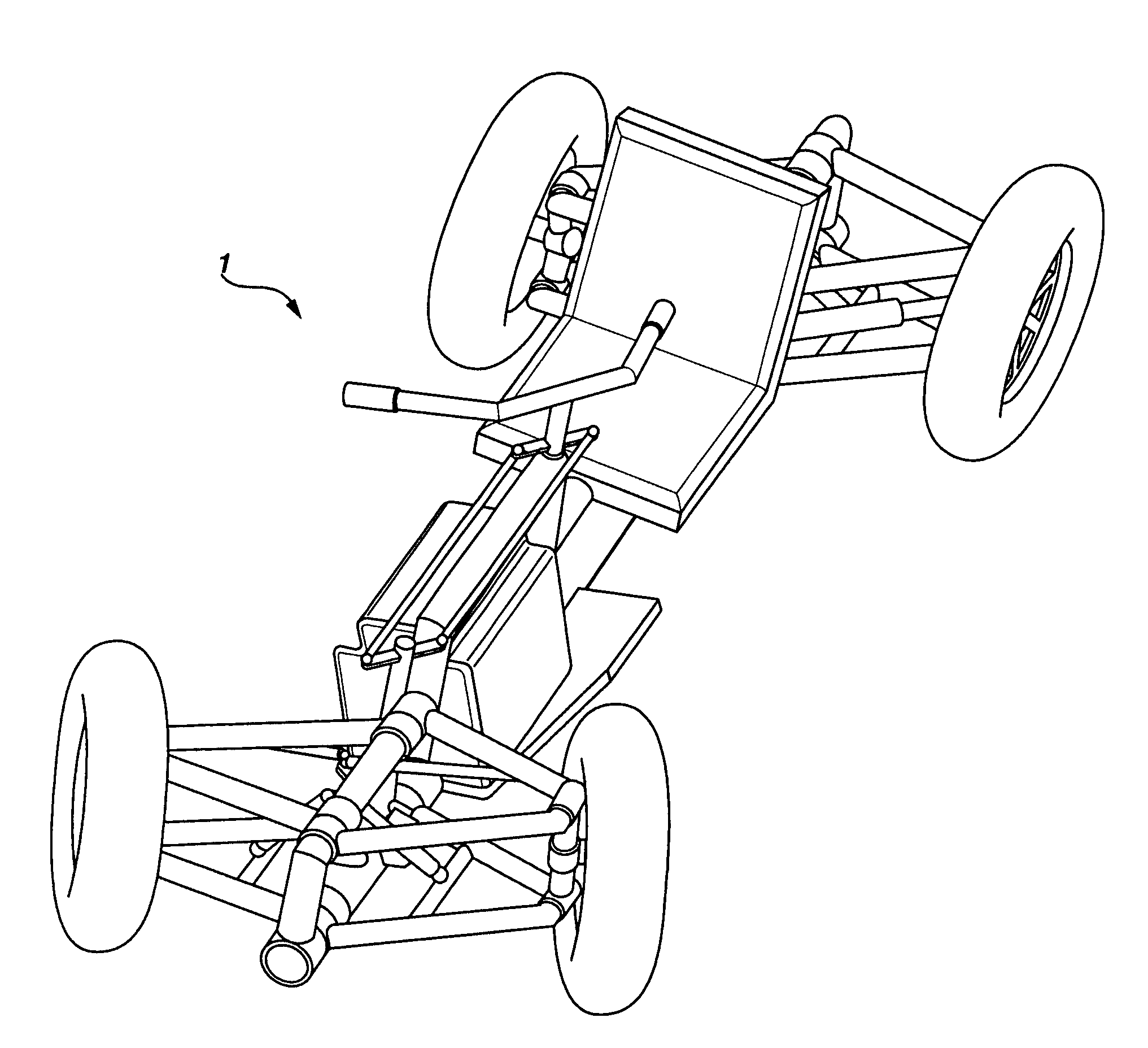
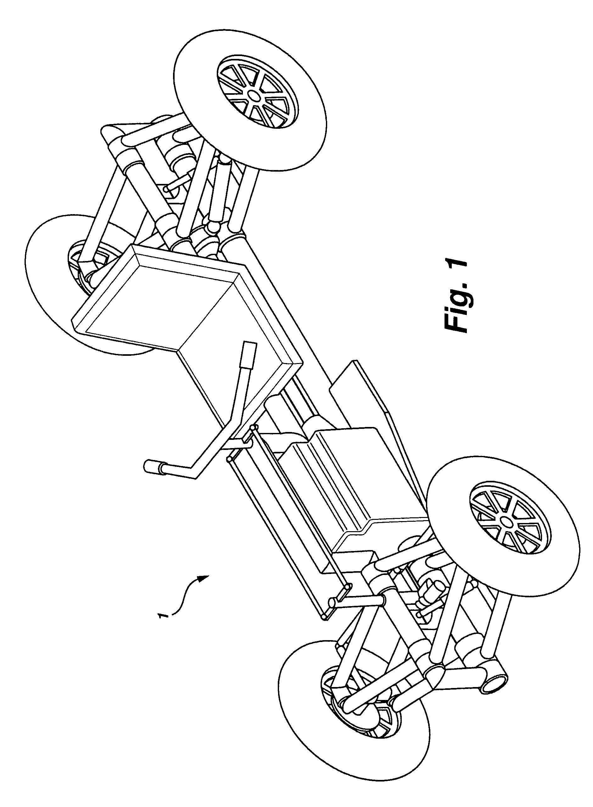
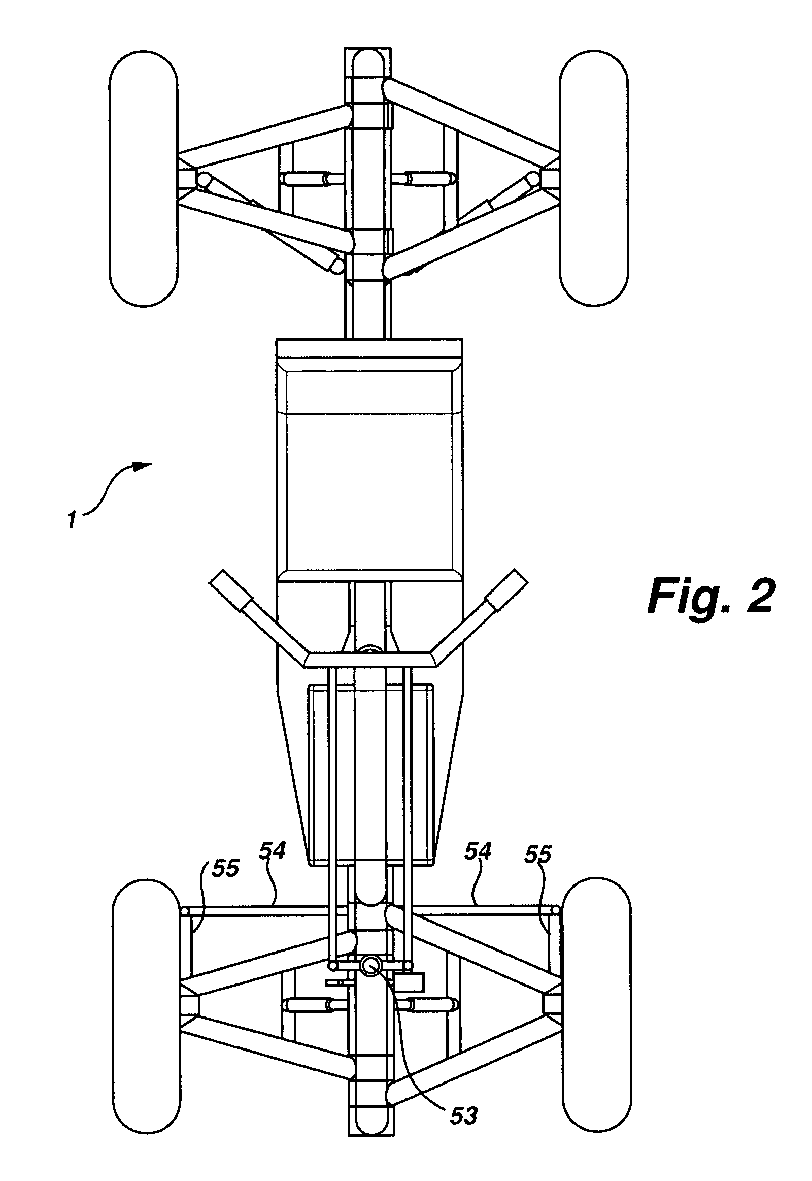
[0041]A suspension system 1 for a tilting vehicular chassis is shown in a neutral posture, wherein the vehicle may be parked or moving directionally forward, in FIGS. 1 and 2. FIG. 5 represents the suspension system 1 in the posture of a tilted turn. The articulation of suspension system 1 under certain road and steering conditions, as viewed frontally, is shown in FIGS. 7-9. FIG. 7 represents the neutral posture; FIG. 8 shows the suspension system encountering a shock load, as when traversing a road bump; and FIG. 9 illustrates the chassis in a tilting posture, as when banking for a right-hand turn.

[0042]The details of suspension system 1 are best shown in FIGS. 3 and 4. FIG. 4 illustrates a non-tilting frame 10. Non-tilting frame 10 is comprised of a first longitudinal member 15 having a first axis 11. First horizontal members 12 are disposed about the first axis 11 and are rotatably attached, in oppositely-directed pairs, at the front and rear of first longitudinal member 15. In ...


PUM


Abstract

A suspension system for a tilting vehicular chassis based on more than three wheels separates a tilting component of the chassis from a non-tilting component. The non-tilting component provides a means for powering the vehicle with automotive-type engine and drive train options, while the tilting component provides the turning stability necessary for a narrower wheel base. The narrower wheel base benefits fuel economy. The multiplicity of wheels, and the breadth of platform thus enabled, permits shelter and comfort features for the occupant not otherwise available on a typical two-wheel chassis.

Description

CROSS-REFERENCE TO RELATED APPLICATIONS[0001]This is a Continuation-in-Part of U.S. patent application Ser. No. 11 / 590,475, filed Nov. 1, 2006, claiming priority to Provisional Application 60 / 731,415, filed Oct. 31, 2005.FIELD OF THE INVENTION[0002]This invention relates to tilting chassis systems for vehicles, and more particularly to a suspension system for a tilting chassis having more than three wheels.BACKGROUND OF THE INVENTION[0003]Motorcycles exhibit handling characteristics which are superior in many ways over automobiles, and have less aerodynamic drag and reduced rolling resistance as compared with standard automobiles and automobile tires. Reduced aerodynamic and rolling resistance result in improved fuel economy and vehicle performance. The preferred embodiment of the invention has four tires and is therefore capable of carrying a higher gross weight than a typical motorcycle with two tires. The vehicle can accommodate a larger and heavier engine, heavier fuels and load...

Claims


Application Information

Patent Timeline
Patent Type & Authority Patents(United States)
IPC IPC(8): B60G21/00
CPCB60G3/20B60G21/002B60G2200/144B60G2300/45B60G2204/148B60G2204/422B60G2204/143B62K5/01B62K5/08B62K5/10
Inventor DIEZIGER, DAVID DOUGLAS
Owner DIEZIGER HELEN IRENE
Why Eureka
Try Eureka