Optical switch and optical crossconnect apparatus

a technology of optical cross-connect and optical switch, which is applied in the direction of electromagnetic transmission, multi-component communication, wavelength-division multiplex system, etc., can solve problems such as restrictions, and achieve the effects of reducing the hardware of the optical switch, facilitating expansion of the optical switch scale, and simplifying control

Inactive Publication Date: 2011-01-25
HITACHI LTD
View PDF4 Cites 9 Cited by
  • Summary
  • Abstract
  • Description
  • Claims
  • Application Information

AI Technical Summary

Benefits of technology

[0016]An interface with an optical transmission line is connected to a base switch through an optical circulator, thereby enabling the interfaces connected to the base switch to be arbitrarily connected. Further, by constructing in such a manner that the optical signal which is transmitted from the interface toward the base switch is guided to an expanding switch by a selector, the interfaces which are connected to the expanding switch but are not connected to the same base switch can be also arbitrarily connected.
[0017]According to an optical switch and an optical crossconnect apparatus of the invention, by connecting three optical switches of a scale of (k×k) by using a selection switch and optical circulators, the connection of 2k interfaces can be realized by the elements of the number smaller than that in the case of the 3-stage configuration in the related art. Therefore, an optical switch in which hardware of the optical switch can be reduced, control can be simplified, and a scale of the optical switch is expandable can be realized.

Problems solved by technology

However, in the case of configuring the optical switch of the large scale by combining the optical switches of the small scale, since the plurality of optical switches are connected, a restriction occurs in the paths of the optical signals which can be set and there are lines which cannot be connected.

Method used


Image

  • Optical switch and optical crossconnect apparatus
  • Optical switch and optical crossconnect apparatus
  • Optical switch and optical crossconnect apparatus

Examples


Embodiment Construction

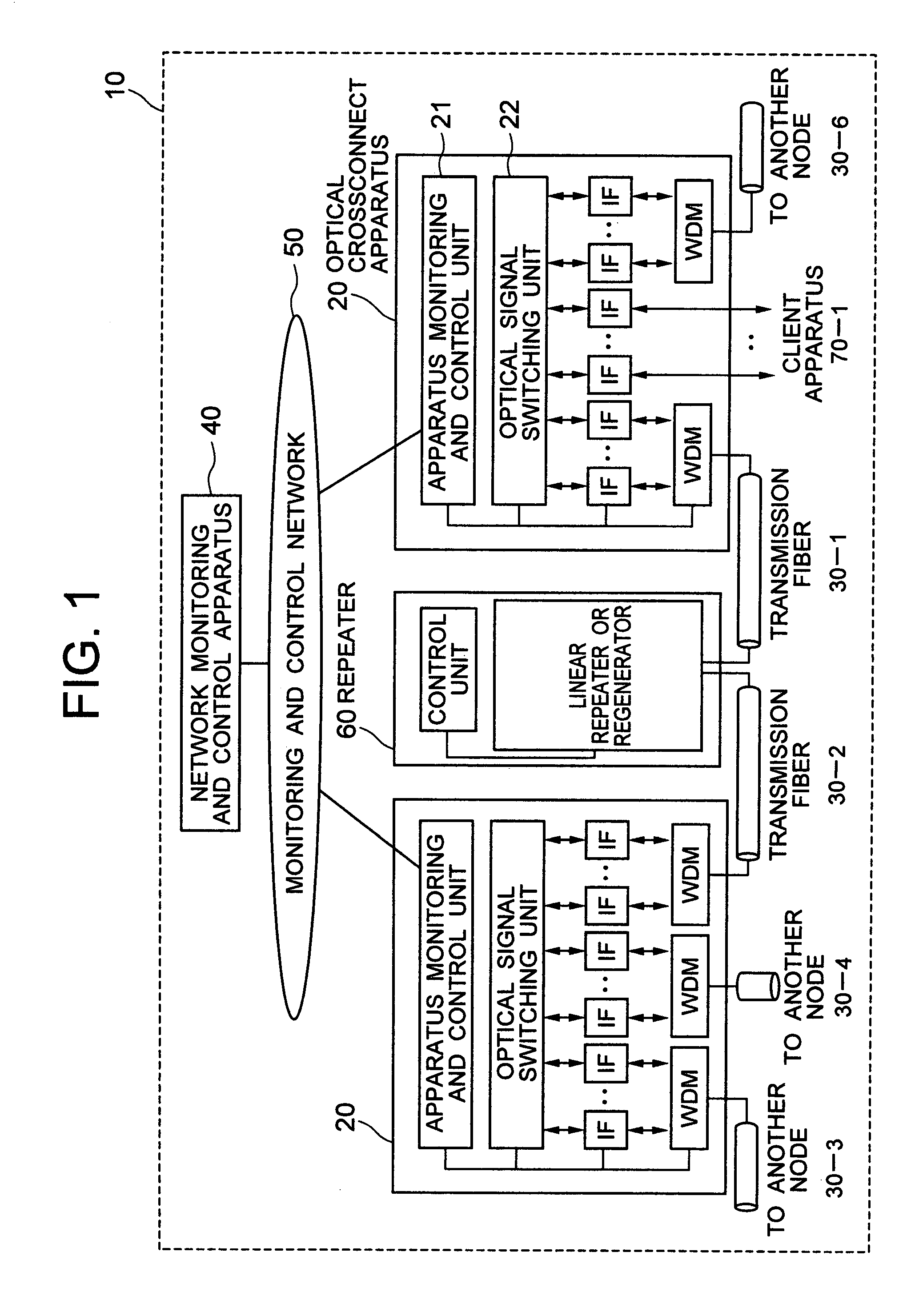
[0027]An optical crossconnect apparatus as an embodiment of the invention will be described in detail hereinbelow with reference to the drawings. FIG. 1 is a diagram showing an example of an optical network to which the optical crossconnect apparatus of the invention can be applied. In FIG. 1, an optical network 10 is constructed by: an optical crossconnect apparatus 20; a transmission line 30 connecting the optical crossconnect apparatus 20; a network monitoring and control apparatus 40; a monitoring and control network 50 for transmitting and receiving a monitoring and control signal between the network monitoring and control apparatus 40 and the optical crossconnect apparatus 20; and a repeater 60 provided between transmission lines. In the embodiment, the number of transmission line fibers which are connected to the optical crossconnect apparatus 20 is merely shown as an example. A larger number of transmission line fibers may be accommodated in the optical crossconnect apparatu...


PUM


Abstract

An optical switch is constructed by: first and second optical switches each having ports of k inputs and k outputs; a third optical switch of k inputs and k outputs which can perform a bi-directional transmission; 2k first optical circulators; 2k second optical circulators; and 2k selecting switches. First to kth interfaces are connected by the first optical switch. (k+1)th to 2kth interfaces are connected by the second optical switch. The first to kth interfaces are connected to one of the (k+1)th to 2kth interfaces by the third optical switch. An optical crossconnect apparatus is also provided.

Description

CLAIM OF PRIORITY[0001]The present application claims priority from Japanese application JP-2006-321018 filed on Nov. 11, 2006 the content of which is hereby incorporated by reference into this application.BACKGROUND OF THE INVENTION[0002]1. Field of the Invention[0003]The invention relates to an optical transmission system and an optical network which are used in a trunk network that covers communication among foreign countries or in the whole country, an intraprefecture network, or the like and, more particularly, to an optical crossconnect apparatus for making a path switching and a bandwidth management of an optical signal.[0004]2. Description of the Related Art[0005]The realization of a large transmission capacity of a communication network is progressing due to a rapid increase in recent data traffic represented by the Internet. Nowadays, since the realization of the optical transmission has been put into practical use, the transmission capacity is increasing by using a time d...

Claims


Application Information

Patent Timeline
Patent Type & Authority Patents(United States)
IPC IPC(8): H04J14/00H04B10/07H04B10/032H04B10/077H04B10/27H04J14/02H04Q3/52
CPCH04Q11/0005H04Q2011/0035H04Q2011/0039H04Q2011/0052H04Q2011/0083H04Q2011/0098
Inventor FUKASHIRO, YASUYUKI
Owner HITACHI LTD
Why Eureka
Try Eureka