Knee scooter

a knee scooter and scooter body technology, applied in the direction of steering devices, frictional rollers based transmission, cycle equipment, etc., can solve the problem of heavy weight of the steering mechanism, and achieve the effects of easy storage and transportation, increased stability of the knee scooter, and safe sharp turns

Inactive Publication Date: 2011-05-10
ANDERSON MICHAEL DALE
View PDF17 Cites 20 Cited by
  • Summary
  • Abstract
  • Description
  • Claims
  • Application Information

AI Technical Summary

Benefits of technology

[0006]For the present invention, the knee scooter includes an adjustment tube that is selectively engageable between the seat and the first extension of the chassis. When engaging the first extension, the adjustment tube is oriented substantially perpendicular to the chassis plane. Further, during engagement between the adjustment tube and the first extension, the adjustment tube is positioned at a distance “k” from the vertex to off-set the adjustment tube from the centerline of the chassis. In this manner, a user may rest a knee on the seat while propelling the knee scooter with the other leg in the foot-space. Also, the knee scooter is provided with a foot rest attached to the second extension to support the user's propelling leg to allow the user to relax his propelling leg while coasting or being pushed. Further, the foot rest allows the user to center his weight over the chassis centerline to increase stability of the knee scooter. When resting his propelling leg on the foot rest, the user may make sharp turns safely by shifting his weight by adjusting his torso and / or legs.
[0007]For control of the knee scooter, it is provided with a steering mechanism including an elongated front fork assembly. Structurally, the fork assembly includes a rod with a first end and a second end. Also, the steering mechanism includes a steering tube assembly formed with a hollow tube member to receive the rod of the front fork assembly. Importantly, the steering mechanism is lightweight. Coupled with the knee scooter design, the user may stand on his propelling leg on the chassis centerline and lift the front end of the knee scooter to pivot around in extremely tight quarters if necessary.

Problems solved by technology

Importantly, the steering mechanism is lightweight.

Method used


Image

  • Knee scooter
  • Knee scooter
  • Knee scooter

Examples


Embodiment Construction

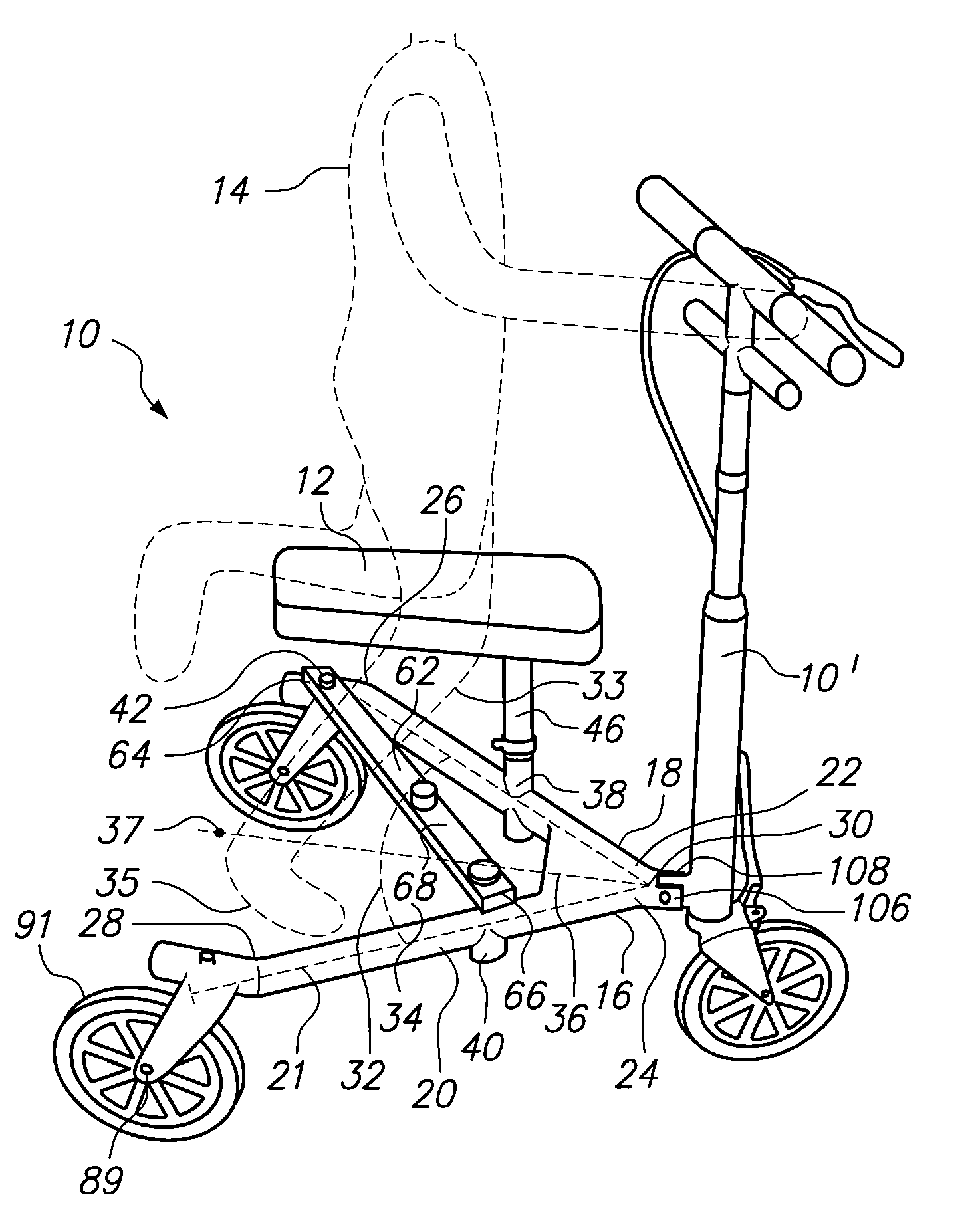
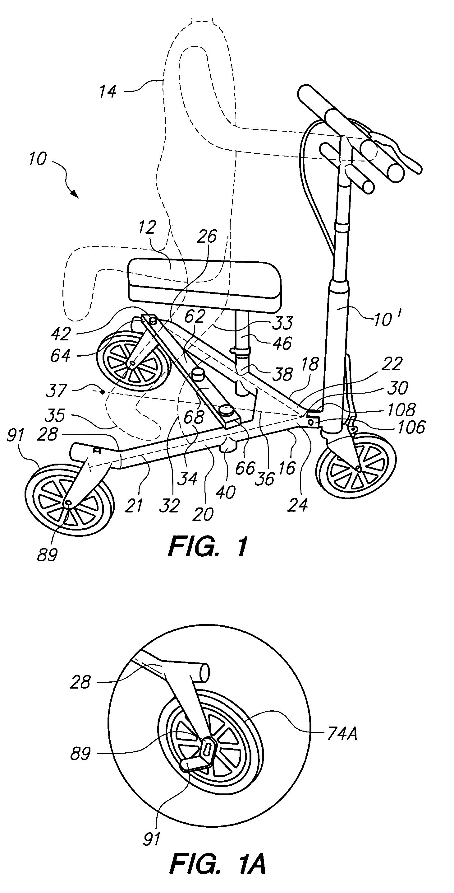
[0019]Referring initially to FIG. 1, a knee scooter, generally designated 10, is shown in position for supporting the knee 12 of a user 14, in accordance with the present invention. Structurally, the knee scooter 10 includes a substantially V-shaped chassis 16 formed from an extension 18 and an extension 20 to define a plane 21. Each extension 18, 20 includes a respective leading end 22, 24 and trailing end 26, 28. As shown, the leading end 22 of extension 18 joins the leading end 24 of extension 20 at a vertex 30 to form an angle 32 (preferably sixty degrees). Further, the extensions 18 and 20 define a foot-space 34 for receiving the user's other leg 33 and foot 35. For the invention, the angle 32 and foot-space 34 are bisected by a chassis centerline 36. As shown, the centerline 36 passes through a midpoint 37 between the trailing ends 26, 28.

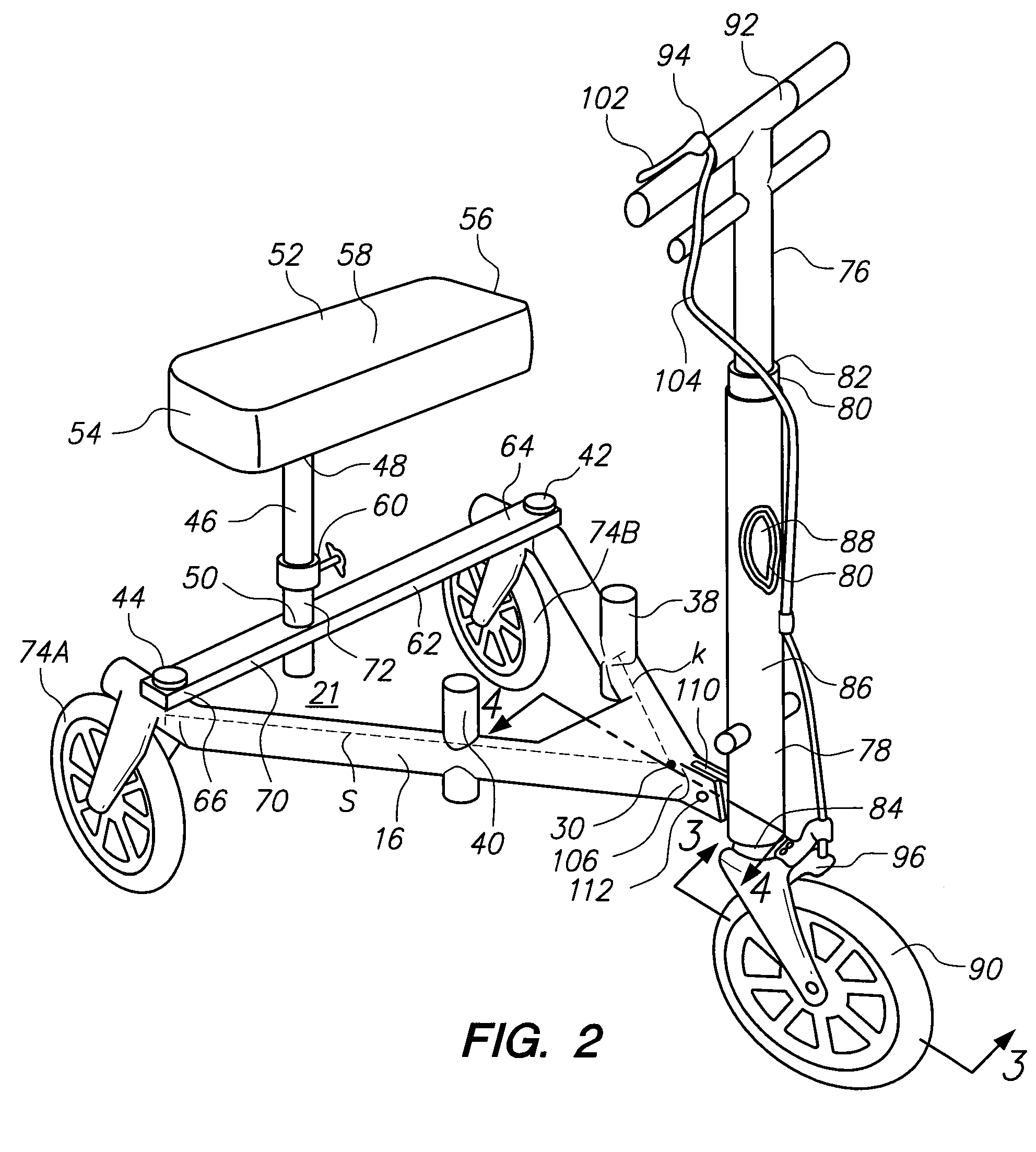
[0020]In FIG. 2, the chassis 16 includes a forward pair of mounts 38 and 40 and a rear pair of mounts 42 and 44. As shown, each of the forwa...


PUM


Abstract

A knee scooter includes a substantially V-shaped chassis formed by a pair of extensions joined together at a vertex. At the vertex, the extensions form an angle of about sixty degrees. Further, the extensions establish a foot-space in the interior of the angle and define a chassis centerline that bisects the angle. An adjustment tube is selectively engageable with the first extension of the chassis to orient the adjustment tube substantially perpendicular to the plane of the chassis. Further, engagement with the first extension off-sets the adjustment tube from the centerline of the chassis. In use, a user rests one knee on the seat while propelling the knee scooter with his / her other leg in the foot-space.

Description

FIELD OF THE INVENTION[0001]The present invention pertains generally to devices and methods used to facilitate movement by injured or disabled persons. More particularly, the present invention pertains to devices and methods that use a wheeled vehicle to support a person with one injured foot or lower leg during self-propelled movement. The present invention is particularly, but not exclusively, useful for mobilizing such an injured or disabled person in an upright ambulatory position.BACKGROUND OF THE INVENTION[0002]Often during rehabilitation of a foot or leg injury, a person cannot put weight on his / her injured limb. Typically, the person may use crutches which shift weight-bearing responsibilities to the person's upper body. Alternatively, the person may remain in a seated position for movement in a wheel chair. Another option is the use of a knee walker or knee scooter. Such a vehicle provides a support for the user's knee. Further, the support is typically mounted on wheels an...

Claims


Application Information

Patent Timeline
Patent Type & Authority Patents(United States)
IPC IPC(8): B62M1/00
CPCB62K3/002B62K9/00B62K2015/005
Inventor ANDERSON, MICHAEL DALE
Owner ANDERSON MICHAEL DALE
Why Eureka
Try Eureka