
Device and method to prevent the exsiccation of fluid products in a dispensing machine for said products
a technology of fluid products and dispensing machines, which is applied in the direction of liquid bottling, liquid dispensing, combustion process, etc., can solve the problems of coagulation, insufficient to prevent exsiccation, and mismeasured quantities delivered
- Summary
- Abstract
- Description
- Claims
- Application Information
AI Technical Summary
Benefits of technology
Problems solved by technology
Method used
Image


Examples
Embodiment Construction
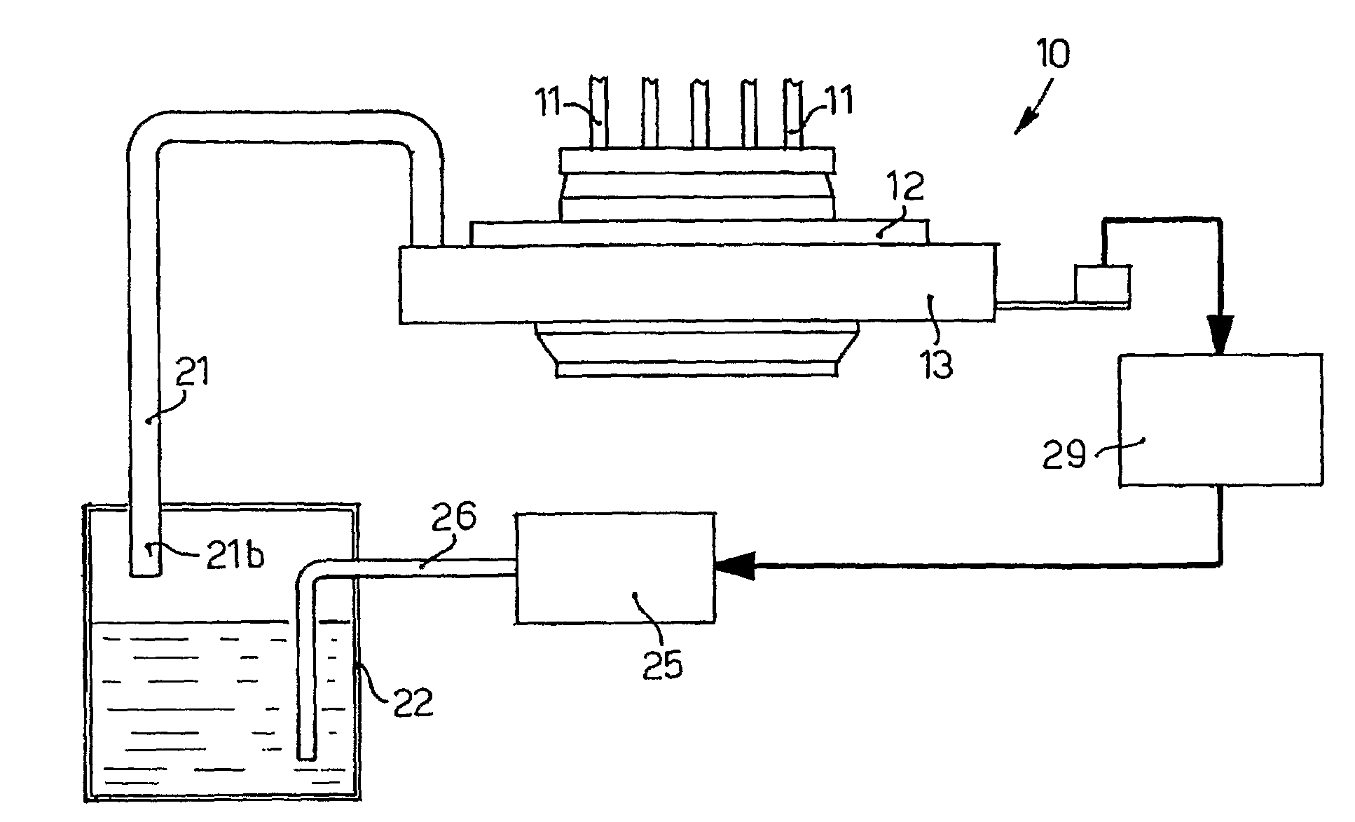
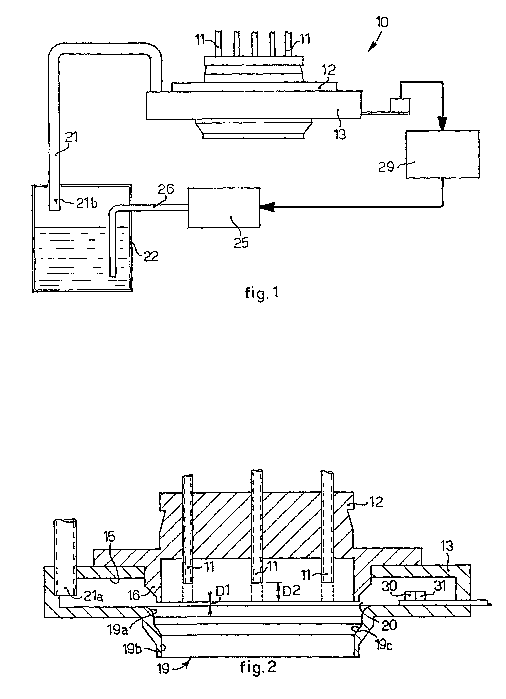
[0028]With reference to FIGS. 1 and 2, a device 10 according to the present invention to prevent the exsiccation of fluid products in correspondence with the delivery nozzles 11 of a delivery head 12 in a dispensing machine for said fluid products comprises an annular element 13 arranged substantially coaxial with the delivery head 12.
[0029]The annular element 13 is shaped so as to comprise an annular chamber 15 (FIGS. 2 and 4), which extends around the lower end 16 of the delivery head 12, and a compartment 19 arranged below the latter.
[0030]The compartment 19 (FIG. 2) is shaped so as to have the three following zones: an upper zone 19a, substantially cylindrical and with a diameter greater than the outer diameter of the lower end 16 of the delivery head 12; a lower zone 19b, also substantially cylindrical but with a diameter substantially equal to the inner diameter of the said lower end 16; and an intermediate zone 19c, flared and connecting the two zones 19a and 19b.
[0031]In th...
PUM
| Property | Measurement | Unit |
|---|---|---|
| distance | aaaaa | aaaaa |
| distance | aaaaa | aaaaa |
| distance | aaaaa | aaaaa |
Abstract
Description
Claims
Application Information