Mounting apparatus for expansion card

Inactive Publication Date: 2011-07-26
HON HAI PRECISION IND CO LTD
View PDF5 Cites 6 Cited by
  • Summary
  • Abstract
  • Description
  • Claims
  • Application Information

AI Technical Summary

Problems solved by technology

However, the plate-shaped locking members may block airflow to the expansion ca

Method used


Image

  • Mounting apparatus for expansion card
  • Mounting apparatus for expansion card
  • Mounting apparatus for expansion card

Examples


Embodiment Construction

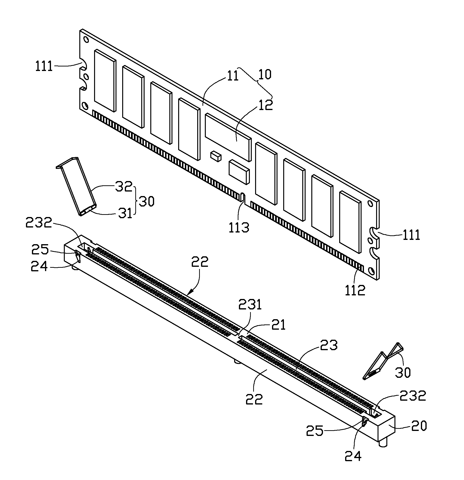
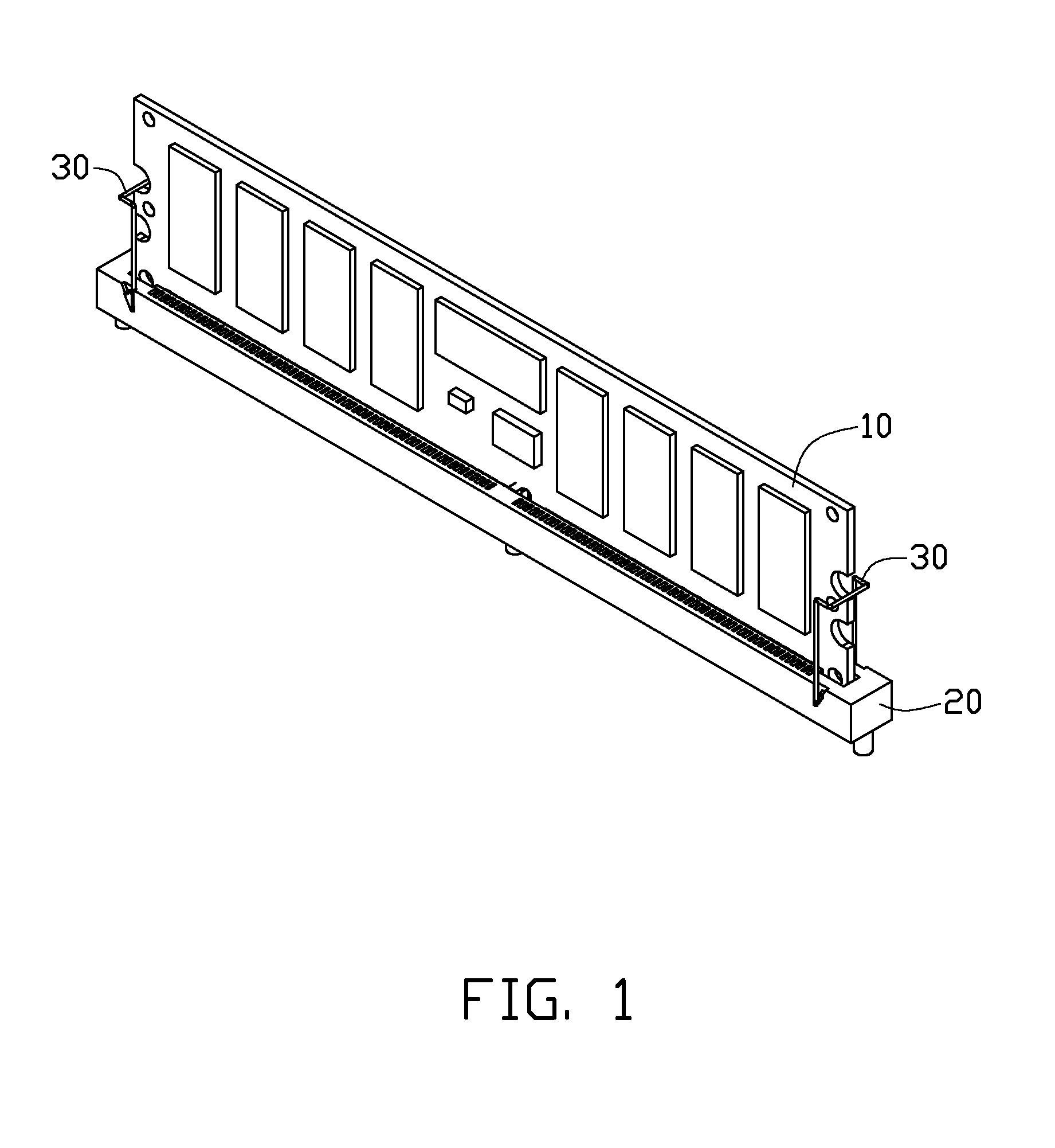
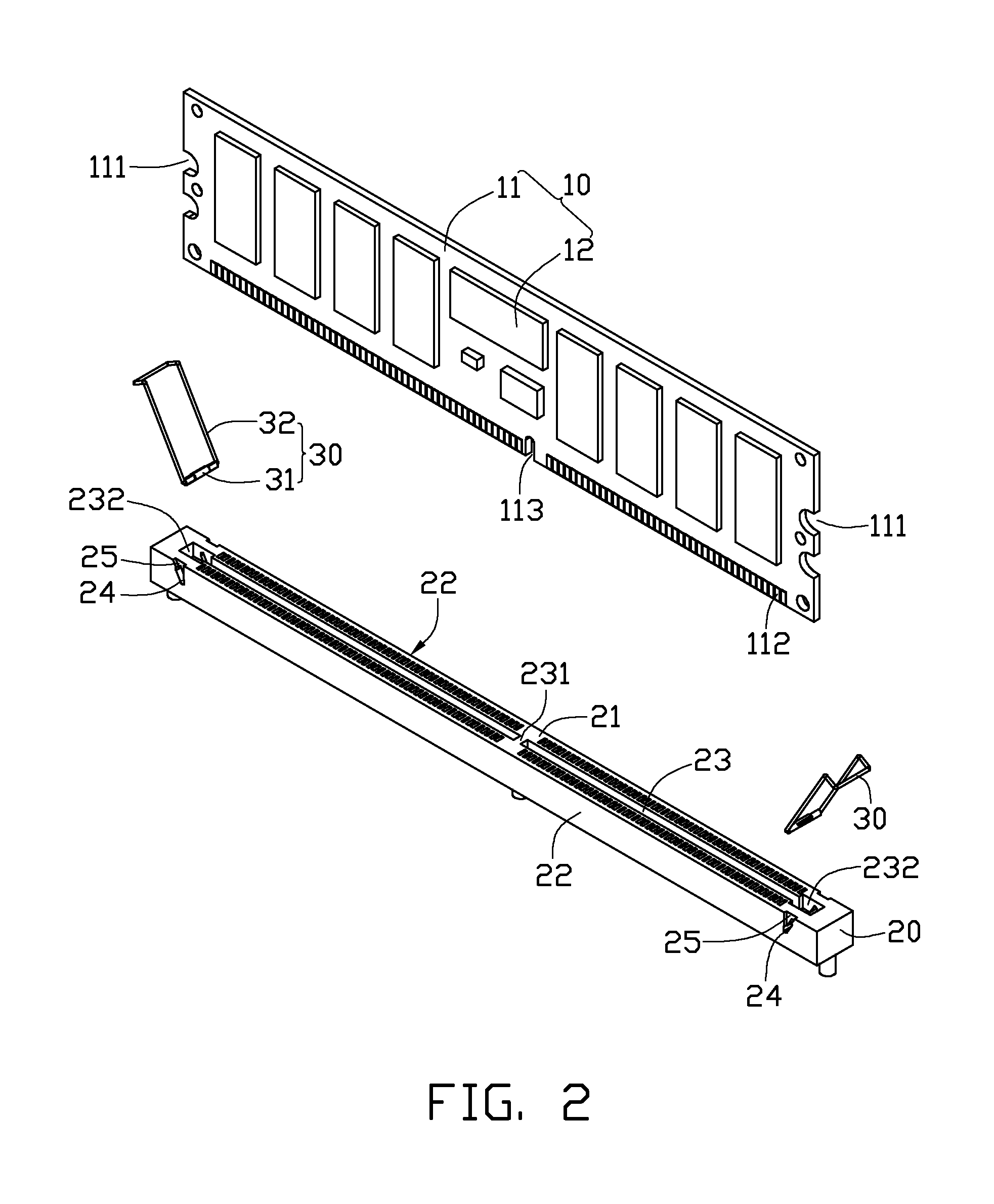
[0015]Referring to FIGS. 1-2, a mounting apparatus according to an exemplary embodiment of the present disclosure is shown. The mounting apparatus is used for mounting an expansion card 10 thereon. The mounting apparatus includes an electrical connector 20, and two latching mechanisms 30 respectively arranged at two opposite ends of the connector 20. The connector 20 is installed on a mainboard (not shown) to electrically connect the expansion card 10 with the mainboard.

[0016]The expansion card 10 includes an elongated main body 11, and a plurality of chips 12 mounted on the main body 11. The main body 11 of the expansion card 10 has two opposite ends, and two spaced arc-shaped recesses 111 defined in each end thereof. A plurality of horizontally spaced electrical pins 112 are provided on a bottom portion of the expansion card 10.

[0017]The connector 20 is elongated, and includes two long sidewalls (not labeled) parallel to each other. The connector 20 includes a top surface 21, and ...


PUM


Abstract

An exemplary mounting apparatus includes a connector and two latching mechanisms connected to two opposite ends of the connector. The connector defines a slot in a top surface thereof, and two sliding grooves in two opposite side surfaces thereof. Each sliding groove extends though the two side surfaces. Each latching mechanisms includes a guide pin and a latching member. The guide pin is slidably received in a corresponding sliding groove. The latching member includes a latching portion for engaging with an expansion card, two feet connected to two ends of the guide pin, and two connecting arms each connected between one end of the latching portion and a corresponding foot. When the guide pin is pulled by the latching member to move from a bottom end to a top end of the sliding groove, the expansion card is pushed out of the slot of the connector by the guide pin.

Description

BACKGROUND[0001]1. Technical Field[0002]The disclosure generally relates to mounting apparatuses; and more particularly to a mounting apparatus for an expansion card.[0003]2. Description of Related Art[0004]Generally, an expansion card such as a memory card is fixed on a circuit board of an electronic device by a mounting apparatus. The electronic device may for example be a computer or a server. The mounting apparatus includes an electrical connector, and two plate-shaped locking members disposed at two opposite ends of the connector for clamping two opposite ends of the expansion card. However, the plate-shaped locking members may block airflow to the expansion card. In particular, a circuit board may have a plurality of expansion cards fixed thereon, with the expansion cards parallel and adjacent to each other. In this arrangement, the locking members of the mounting apparatuses block air from flowing into and out of a space between each two adjacent expansion cards. This reduces...

Claims


Application Information

Patent Timeline
IPC IPC(8): H01R13/62
CPCH01R12/721H01R13/62988
Inventor SUN, ZHENG-HENG
Owner HON HAI PRECISION IND CO LTD
Why Eureka
Try Eureka