Carriage for a door

a technology for doors and carriages, applied in door/window fittings, multi-purpose tools, construction, etc., can solve the problems of carriages that cannot slide smoothly on the rails, the type of apparatus, and the amount of material being loaded, so as to achieve reliable and straightforward effects

Active Publication Date: 2011-11-01
HETTICH HEINZE GMBH & CO
View PDF24 Cites 31 Cited by
  • Summary
  • Abstract
  • Description
  • Claims
  • Application Information

AI Technical Summary

Benefits of technology

[0006]The apparatus of the invention is intended to support a suspension-type door and compensate for unevenesses, warping and height tolerances of the running rail.
[0007]In addition, the invention is intended to provide a reliable and straightforward fitting between at least the carriage and the rail.
[0008]With respect to one embodiment contemplated for the invention, a suspension bolt is retained on the carriage by a bearing (or similar means) such that it pivots relative to the running rollers. In this embodiment, therefore, it is possible to compensate for unevenesses or twisting of the rail since the suspension bolt may be moved relative to the running rollers. In this example, the suspension bolt may compensate for twisting of the rail if, on the one side, the running surface on the rail is arranged in elevated fashion. As should be apparent, if the bolt is fixedly mounted to the carriage and if one side of the rail is skewed relative to the other side, the bolt would become tilted from a vertical displacement as the carriage moves along the rail. A flexible mounting makes it possible to compensate for such warping of the rail.
[0014]Where the bearing bar incorporates a rounded lower surface, it is contemplated that the bearing bar may be a half cylinder, which is a cylinder divided longitudinally in half at its center. It is contemplated that a half cylinder design makes it possible for the bearing means to pivot smoothly relative to the axial elements.
[0021]It is contemplated that the housing may include elastic dampers on its ends (or end sides). The dampers are expected to damp the action of the carriage when striking against a stopping element.
[0023]In one contemplated embodiment of the apparatus of the invention, it is possible to effectively adjust the height of the door via a suspension bolt. In particular, the suspension bolt may be provided with an external thread above the base of the bearing profile. The external thread may be screwed into a nut secured on the bearing profile. The rail may have two L-shaped webs with a horizontal running surface for the running rollers. A gap may be provided between the webs. A top portion of the suspension bolt may be introduced into this gap, in which case a compact construction is ensured along with height adjustment.

Problems solved by technology

One problem that may arise with this type of apparatus lies in the rail itself.
The rail for securing a suspension-type door may warp or become uneven, thereby introducing deflections and variations.
If the rail becomes warped, deflected, or uneven, the carriage is guided in a skewed manner on the rail, which gives rise to considerable material loading.
Moreover, as should be apparent, once the carriage becomes skewed, it is no longer possible for the carriage to slide smoothly on the rail.
Of course, it remains possible that the carriage may jam if the rail is skewed or if warped, deflected, or uneven portions of the rail exceed predetermined tolerances.

Method used


Image

  • Carriage for a door
  • Carriage for a door
  • Carriage for a door

Examples


Embodiment Construction

[0044]The discussion that follows encompasses one or more embodiments that are considered exemplary of the scope of the invention. The embodiments are provided to illustrate the broad scope of the invention and are not intended to be limiting of the invention.

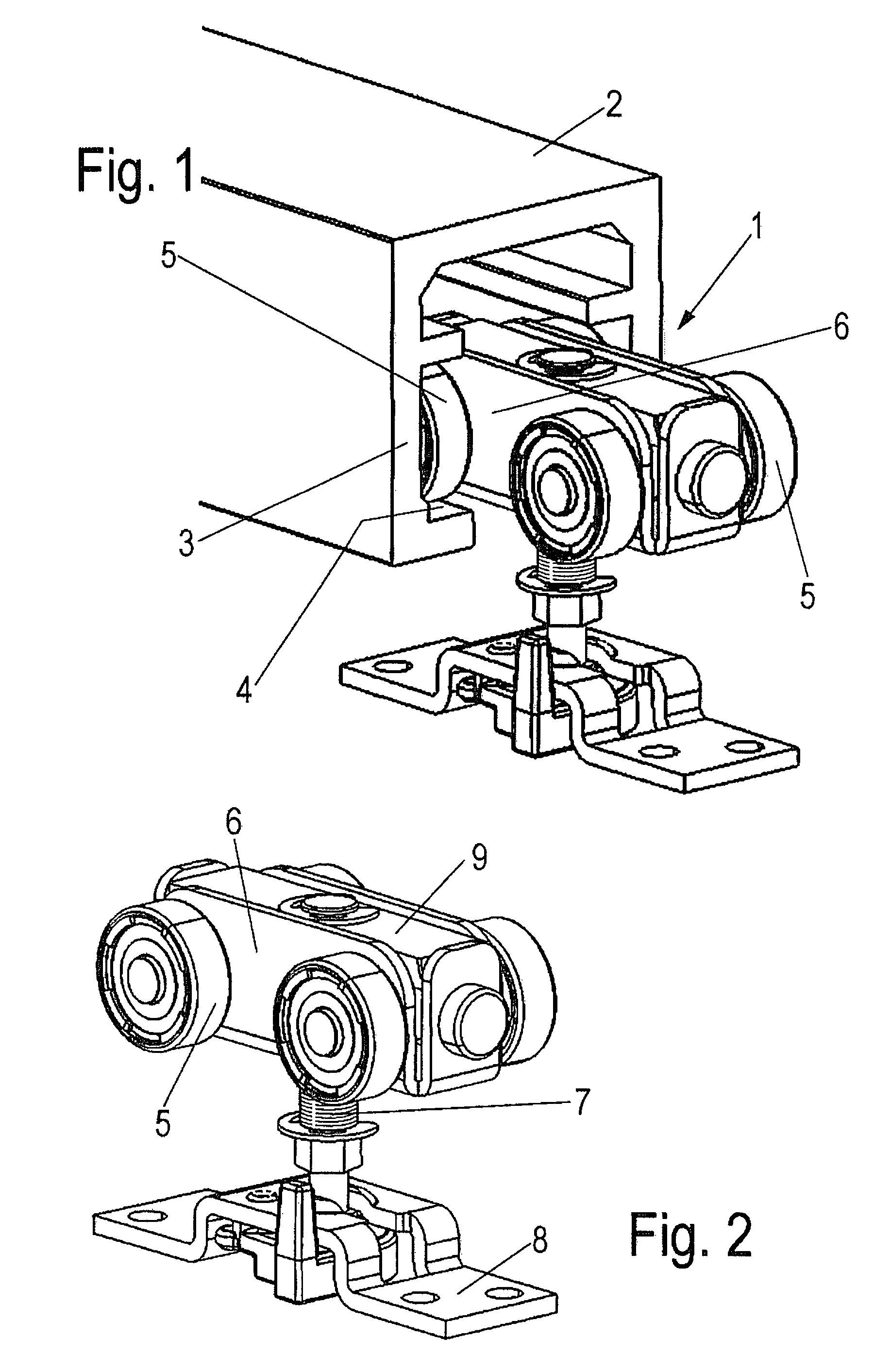
[0045]A carriage 1 is guided on a rail 2 which is of essentially U-shaped design and cross section and has two legs 3. The ends of the legs 3 include inwardly directed webs with running surfaces 4. Running rollers 5, which are arranged adjacent to a housing 6 of the carriage 1, are supported on the running surfaces 4.

[0046]A suspension bolt 7 projects downward from the carriage 1 and is secured on an installation plate 8, which is secured on a suspension-type door. The suspension-type door may be part of a piece of furniture, for example. Of course, the invention is not limited to furniture construction, as should be appreciated by those skilled in the art.

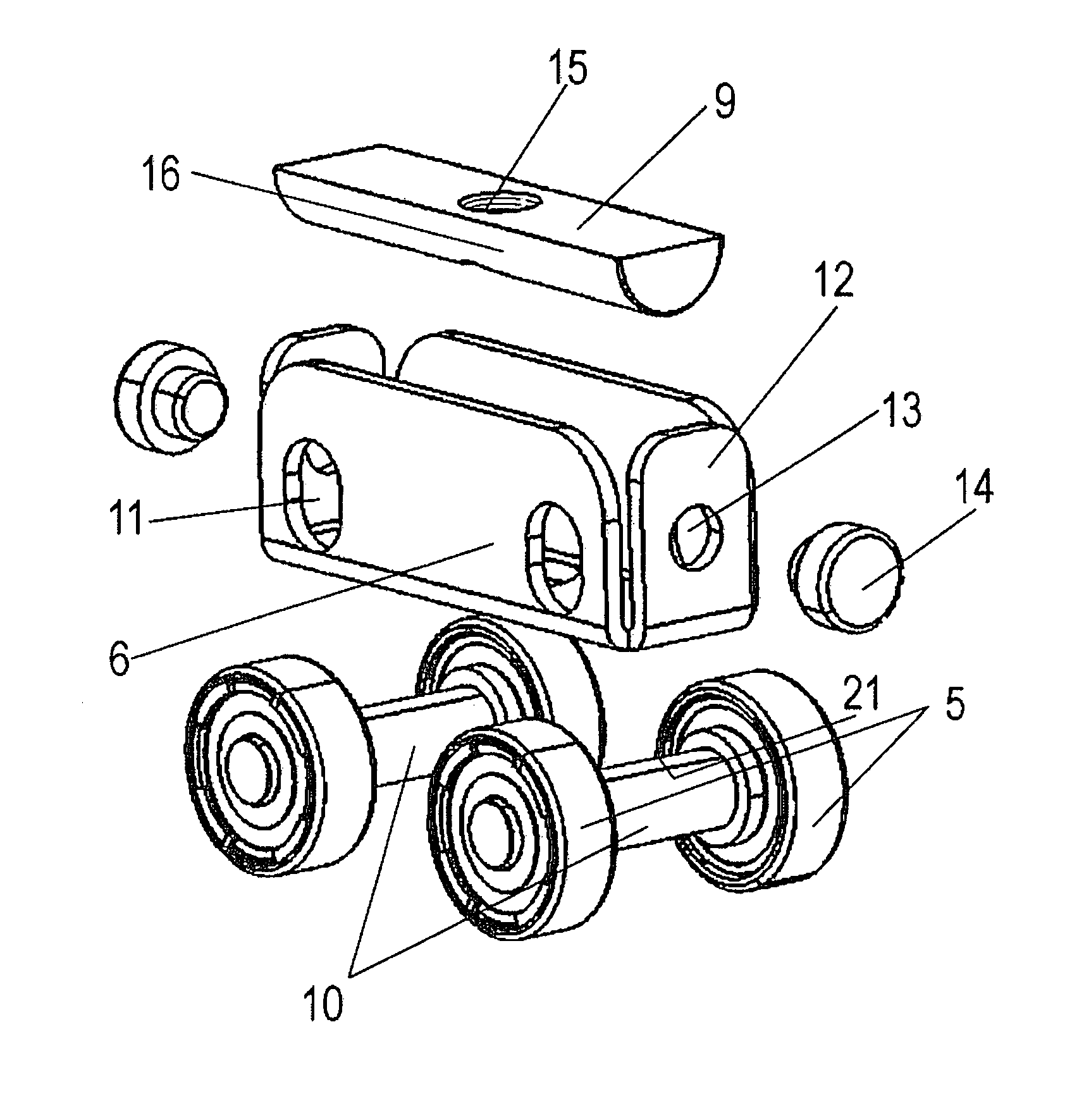
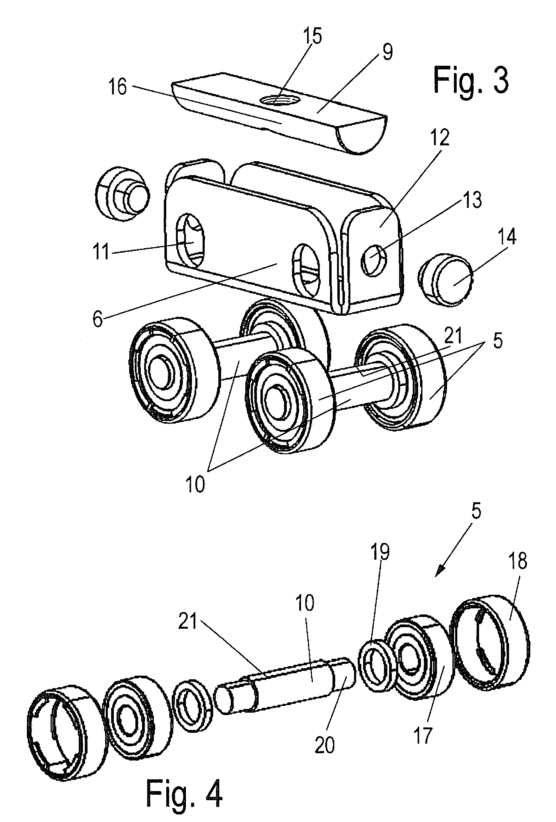
[0047]As can be seen in FIG. 3, the carriage 1 comprises a bearing bar 9...


PUM


Abstract

A carriage for fitting a suspendable door on a rail is described. The carriage includes a housing and at least one running roller disposed on the housing. The running roller is positioned to engage the rail. An installation plate is included that is adapted to be connected to the suspendable door. A suspension bolt is connected between the housing and the installation plate. A portion of the suspension bolt engages a bearing disposed at one end of either the housing or the installation plate. The bearing permits at least angular displacement if the suspension bolt with respect to either the housing or the installation plate.

Description

CROSS-SECTION TO RELATED APPLICATIONS[0001]This is a first-filed U.S. Patent Application and does not rely for priority on any other patent application.FIELD OF THE INVENTION[0002]The present invention relates to a carriage for fitting a suspension-type door on a rail. More specifically, the invention concerns a carriage for fitting a suspension-type door on a rail. The carriage includes a housing or framework on which at least one running roller is mounted on opposite sides. The carriage also includes a suspension bolt which, at one end, is fixed on an installation plate. The bolt may be connected to a suspension-type door at one end and to a bearing means at the other end.DESCRIPTION OF RELATED ART[0003]U.S. Pat. No. 6,209,171 discloses an apparatus for fitting a suspension-type door on a rail. A carriage is provided with a housing to which four rollers are mounted in a rotatable manner. The carriage is connected to a bolt, which is fixed on an installation plate that is fitted on...

Claims


Application Information

Patent Timeline
Patent Type & Authority Patents(United States)
IPC IPC(8): A47H15/00
CPCE05D15/0639E05F5/003E05Y2201/64E05Y2600/10E05Y2600/528E05Y2900/132Y10T16/3834E05Y2201/218E05Y2201/48Y10T16/3831Y10T16/381Y10T16/3828E05Y2600/60
Inventor BURGESS, III, THOMAS EDWARDVOM DORP, JOERGLEIDNER, MICHAEL
Owner HETTICH HEINZE GMBH & CO
Why Eureka
Try Eureka