Stacked pluggable cage having intermediate walls interengaged each other

a pluggable cage and intermediate wall technology, applied in the field of pluggable cages, can solve the problems of difficult to achieve improved emi (electro magnetic interference) shielding, material waste, and shielding member mounted on the bottom wall not being able to provide emi shielding performance to the transceiver away from the bottom wall, so as to achieve the effect of improving emi performance of the transceiver

Inactive Publication Date: 2012-02-28
HON HAI PRECISION IND CO LTD
View PDF15 Cites 16 Cited by
  • Summary
  • Abstract
  • Description
  • Claims
  • Application Information

AI Technical Summary

Benefits of technology

[0010]Accordingly, an object of the present invention is to provide a stacked pluggable cage having a pair of improved intermediate walls interlocked together for achieving an improved EMI performance to the transceivers.
[0012]The intermediate walls inserted in each receiving subspaces would have the flexible fingers in contact with each transceiver to thereby ground each transceiver. Therefore, the EMI shielding performance of the transceivers has been improved.

Problems solved by technology

A spacer is provided between bottom wall of the upper port and a top wall of the lower port would result in material wasted.
Additionally, it is hard to achieve improved EMI (Electro Magnetic Interference) shielding since the spacer would not electrically engage the transceiver.
When the pluggable cage has more than two stacked ports and is adapted for receiving corresponding number of transceivers, the shielding member mounted on the bottom wall could not provide EMI shielding performance to the transceiver away from the bottom wall.

Method used


Image

  • Stacked pluggable cage having intermediate walls interengaged each other
  • Stacked pluggable cage having intermediate walls interengaged each other
  • Stacked pluggable cage having intermediate walls interengaged each other

Examples


Embodiment Construction

[0024]Reference will now be made in detail to the preferred embodiment of the present invention.

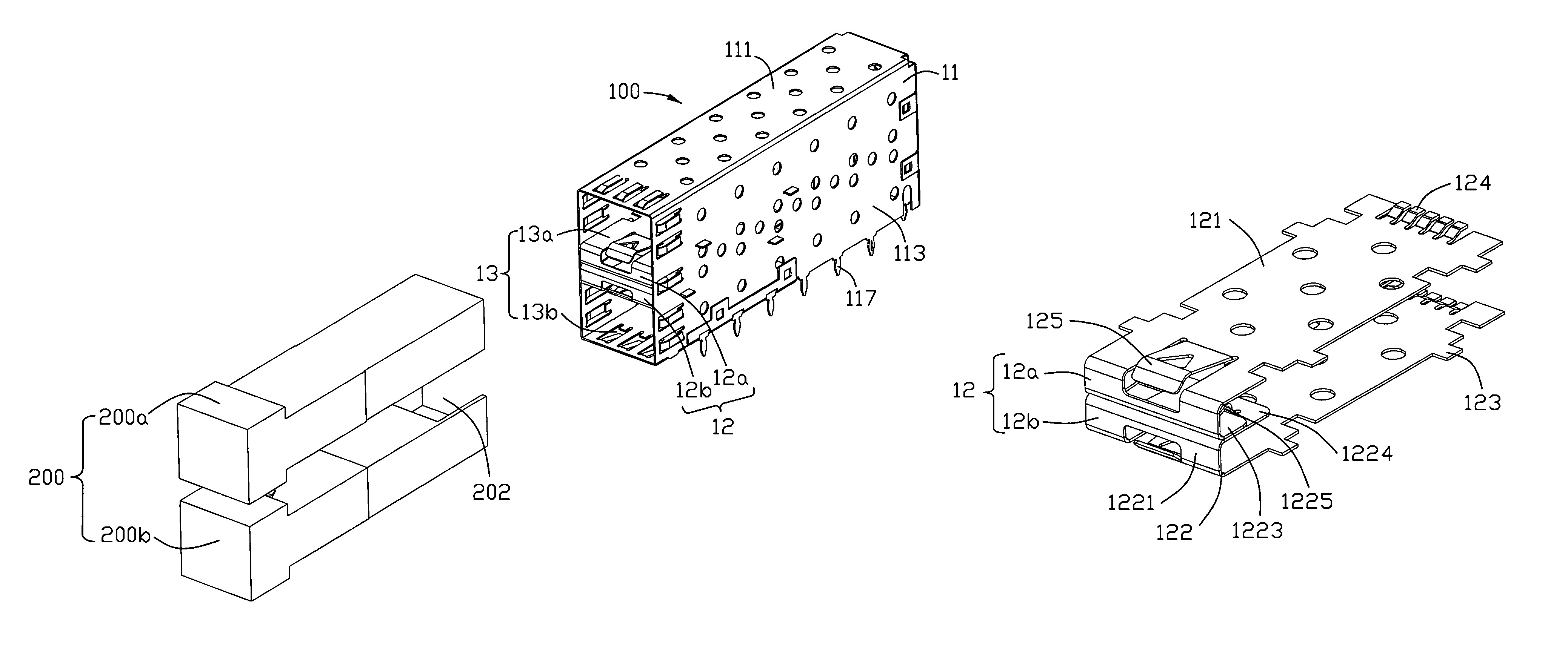
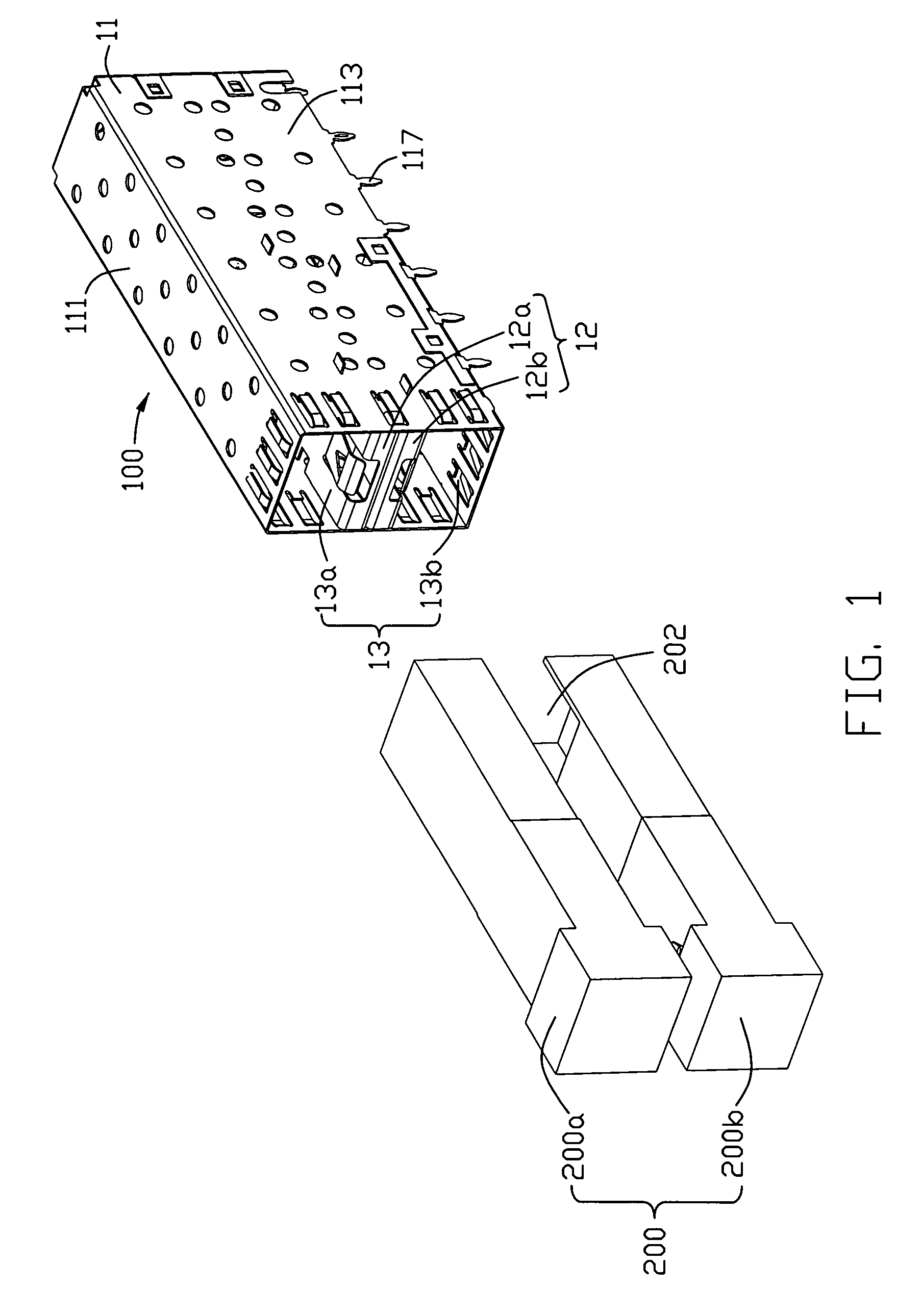
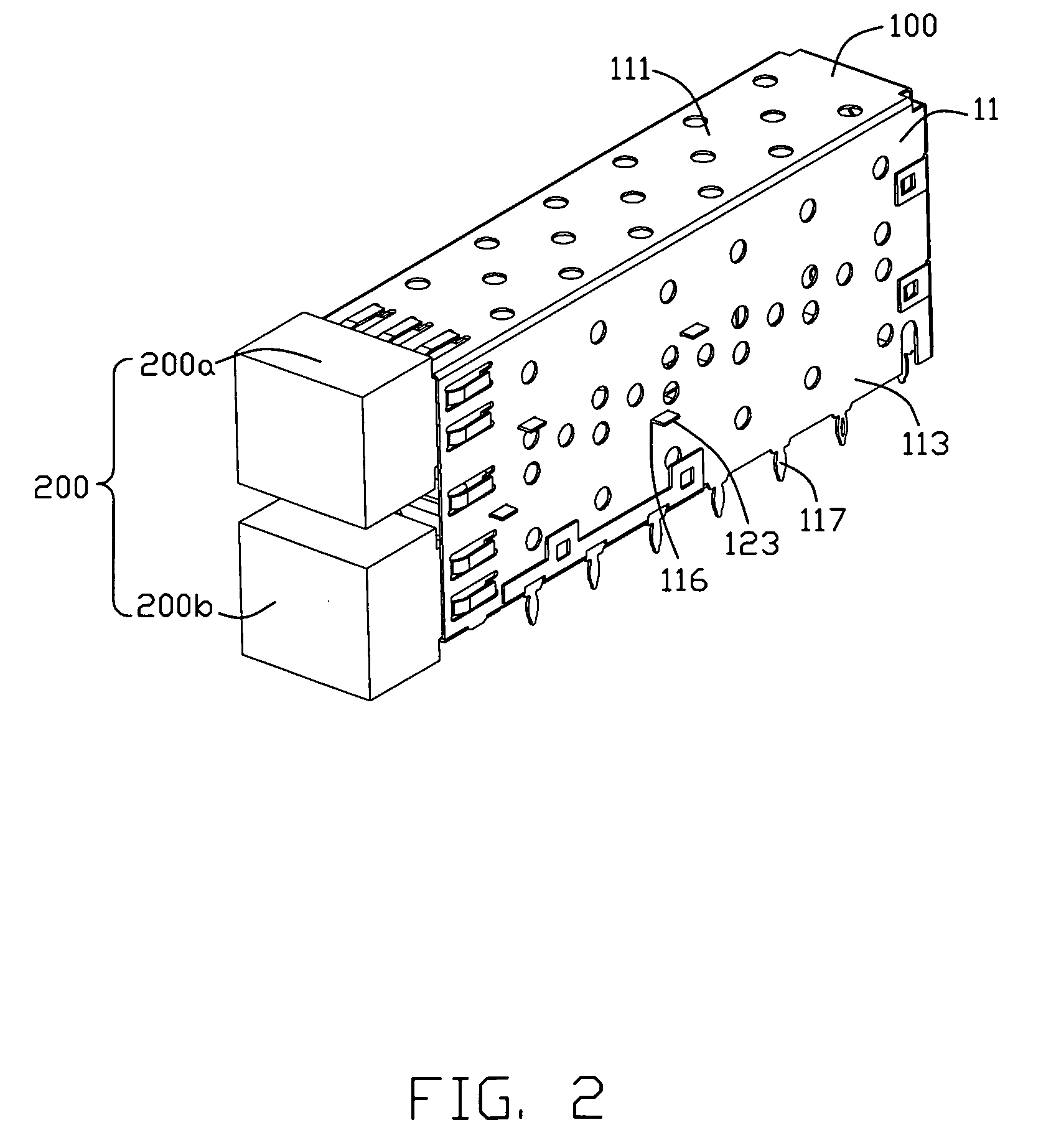
[0025]Referring to FIGS. 1-2, a stacked pluggable cage assembly 100 adapted for receiving two transceiver 200, i.e. upper and lower transceivers 200a, 200b in accordance with the present invention comprises a shielding shroud 11 and a pair of intermediate walls 12. In conjunction with FIGS. 6-7, each transceiver 200 has a locking protrusion 201 formed toward corresponding intermediate wall 12 and a cavity 202 defined at a rear portion thereof and opened toward corresponding intermediate wall 12.

[0026]Referring to FIGS. 1-3, the shielding shroud 11 comprises a top wall 111, a bottom wall 112 defining a bottom opening 115, a pair of side walls 113 and a rear wall 114 interconnected together to define a receiving space 13 therebetween. The side walls 113 have a plurality of engaging slits 116 defined thereon and a plurality of foot portions 117 extending downwardly therefrom.

[0027]Referring ...


PUM


Abstract

A stacked pluggable cage (100) in accordance with the present invention is adapted for receiving two transceivers (200). The stacked pluggable cage includes a shielding shroud (11) defining a receiving space (13), and a first and a second intermediate walls (12) inserted in the shielding shroud. The first and second intermediate walls are disposed adjacent to each other to divide the receiving space into a first and a second receiving subspaces (13a, 13b) for receiving the transceivers respectively. Each intermediate wall has a body portion (121), and a number of flexible fingers (124) extending rearwardly from the body portion and tilting toward corresponding receiving subspace for grounding corresponding transceiver to thereby improve EMI performance.

Description

BACKGROUND OF THE INVENTION[0001]1. Field of the Invention[0002]The present invention relates to a pluggable cage, and more particularly to a stacked pluggable cage having intermediate walls interlocked with each other.[0003]2. Description of Related Art[0004]A standard in development for a next generation of SFP (Small Form-Factor Pluggable transceiver) module, presently being called the XFP (10 Gigabit Small Form-Factor Pluggable transceiver) standard, calls for the transceiver modules to carry data signals at rates up to 10 Gbps.[0005]U.S. Pat. No. 6,972,968 issued to Hwang on Jun. 22, 2004 and U.S. Pat. No. 6,731,519 issued to Hwang on May 4, 2004 discloses an SFP cage. The SFP cage comprises stacked upper and lower ports and a spacer sandwiched between the upper and lower ports. Each port has a top wall, a pair of side walls and a bottom wall connected together to surround the port.[0006]A spacer is provided between bottom wall of the upper port and a top wall of the lower port...

Claims


Application Information

Patent Timeline
Patent Type & Authority Patents(United States)
IPC IPC(8): H05K7/20
CPCG02B6/4201H05K9/0058G02B6/4261G02B6/4277
Inventor BROWN, ROBERT W.BIDDLE, GARY E.
Owner HON HAI PRECISION IND CO LTD
Why Eureka
Try Eureka