High sensitivity differential current transformer for insulation health monitoring

a technology of high-sensitivity differential current and transformer, which is applied in the field of current transformer, can solve problems such as failure to facilitate the assessment of the health of stator insulation while the motor is operating, and the type of faults that may develop in industrial motors

Active Publication Date: 2012-07-10
BAKER HUGHES INC
View PDF8 Cites 17 Cited by
  • Summary
  • Abstract
  • Description
  • Claims
  • Application Information

AI Technical Summary

Problems solved by technology

Also, as will be appreciated, there are various types of faults that may develop in industrial motors during operation.
A majority of these faults in large motors may be related to stator-winding insulation.
Unfortunately, these tests require an outage of the motor from service.
However, these techniques fail to facilitate assessment of the health of stator insulation while the motor is operational.

Method used


Image

  • High sensitivity differential current transformer for insulation health monitoring
  • High sensitivity differential current transformer for insulation health monitoring
  • High sensitivity differential current transformer for insulation health monitoring

Examples


embodiment 56

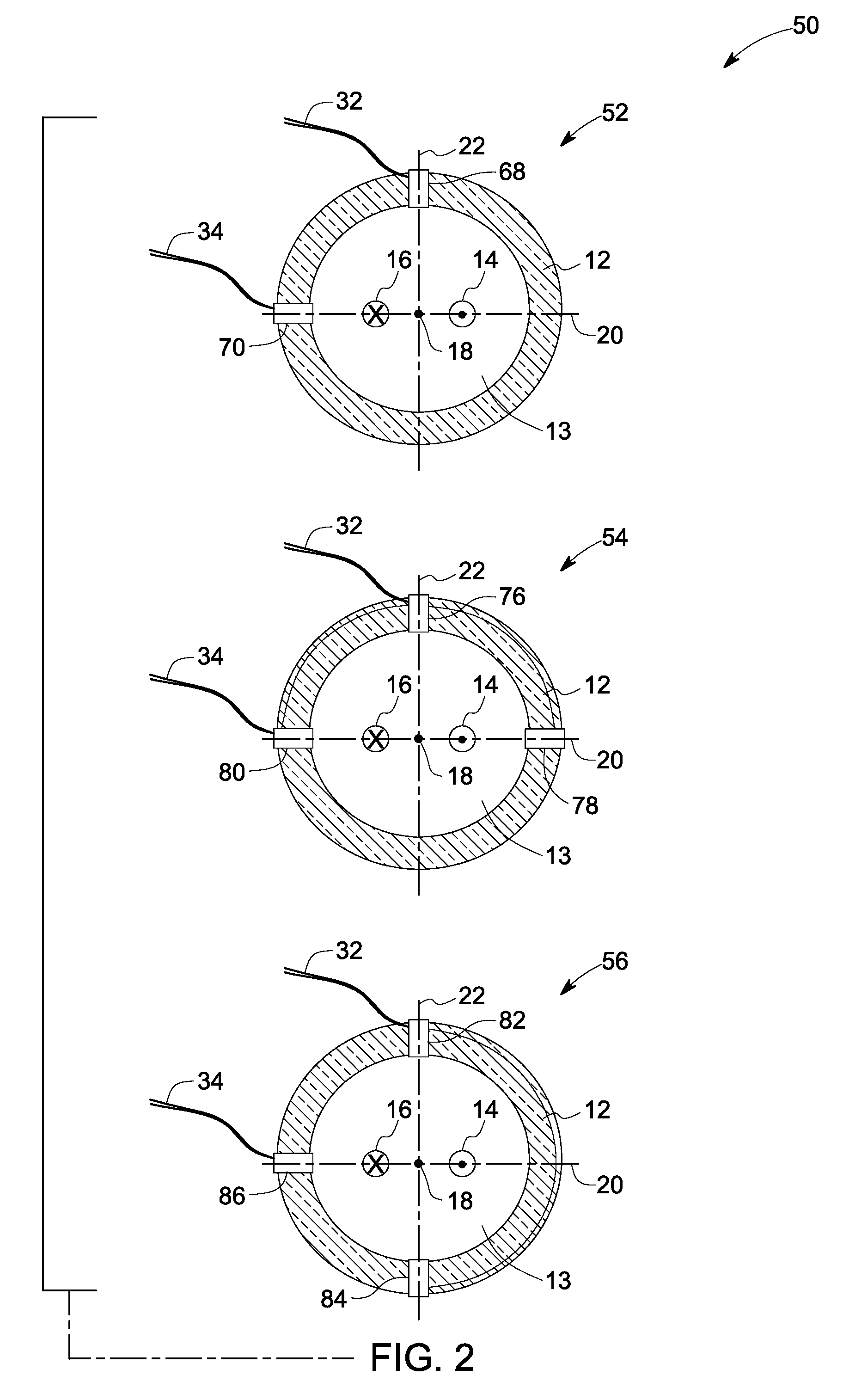
[0030]With continuing reference to FIG. 2, another embodiment 56 of a current transformer is illustrated. In the present embodiment, the magnetic core 12 is depicted as including a plurality of coils 82, 84, 86. As previously noted, with respect to other embodiments of FIG. 2, the pair of conductors 14, 16 pass through a closed central opening 13 of the magnetic core 12. The pair of conductors 14, 16 carry substantially similar currents in opposite directions. In the present embodiment 56, three coils 82, 84, 86 may be disposed on the magnetic core 12 of the current transformer. A first coil 82 and a second coil 84 may be positioned along the magnetic neutral axis 22. In addition, a third coil 86 may be placed on the magnetic core 12 along the reference axis 20 that is perpendicular to the magnetic neutral axis 22. More particularly, the third coil 86 may be placed on the magnetic core 12 at a position that is complementary with respect to the first coil 82 and the second coil 84. F...

embodiment 162

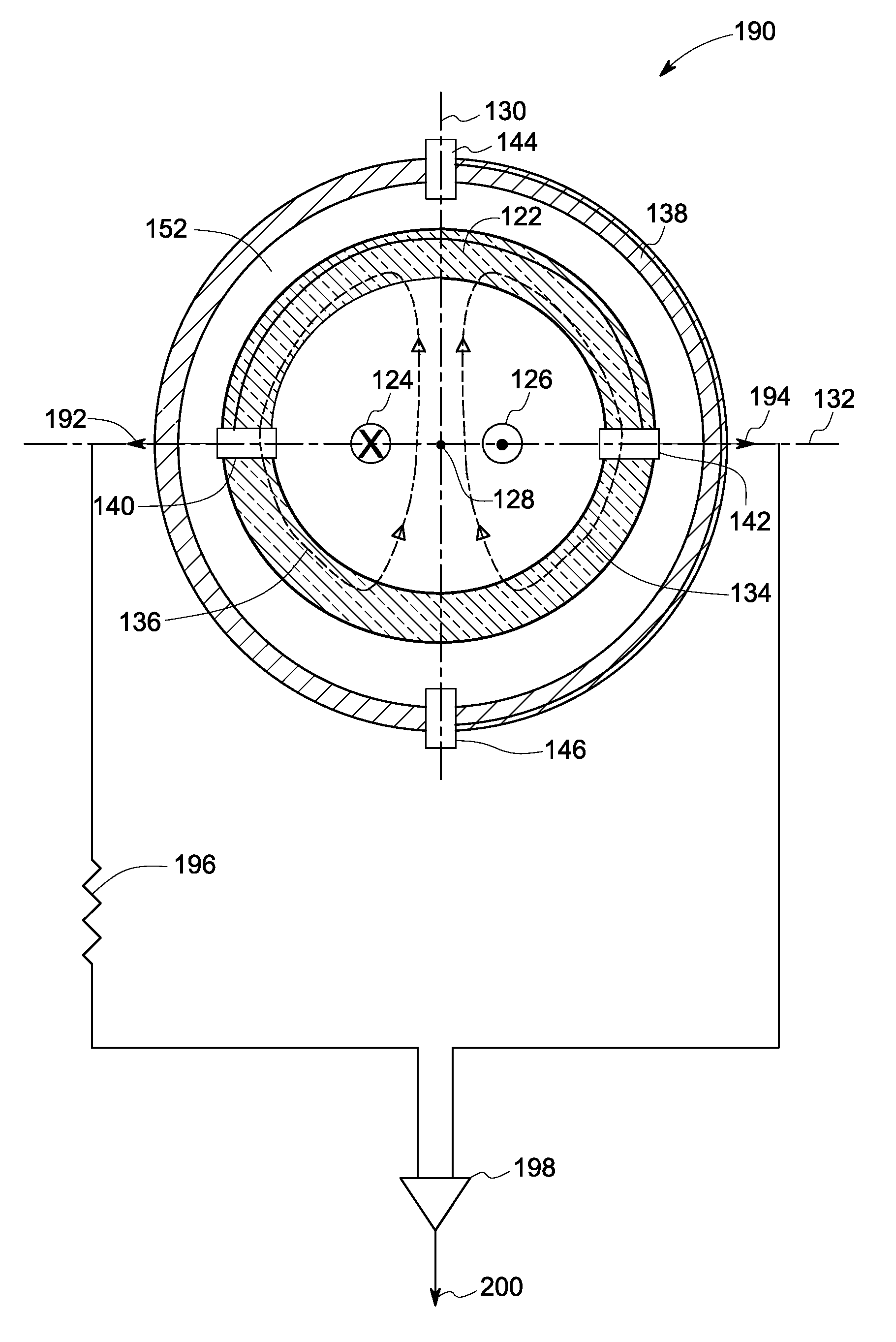
[0041]In accordance with aspects of the present technique, other embodiments of the exemplary current transformer 120 of FIG. 4 are presented in FIG. 5. Turning now to FIG. 5, a diagrammatic illustration 160 of other embodiments 162, 164, 166 of an exemplary dual core current transformer such as the dual core current transformer 120 (see FIG. 4) are presented. Reference numeral 162 is representative of a first alternative embodiment of the exemplary dual core current transformer. The current transformer 162 has a first coil 168 placed along the reference axis 132 on the inner magnetic core 122. A second coil 170 may be disposed on the outer sense core 138 along the magnetic neutral axis 130. The second coil 170 may include a sense coil. In the present embodiment 162, the first coil 168 may be configured to detect partial discharge and load current, while the second coil 170 may be configured to detect leakage current in the exemplary current transformer 162.

[0042]Reference numeral 1...


PUM


Abstract

A current transformer is provided. The current transformer includes a magnetic core having a central opening, at least one pair of conductors extending through the central opening and positioned symmetrically with respect to a center point of the magnetic core, one or more coils disposed on the magnetic core along a magnetic neutral axis of the magnetic core and one or more coils disposed on the magnetic core along a reference axis, wherein the reference axis is substantially perpendicular to the magnetic neutral axis.

Description

BACKGROUND[0001]Embodiments of the present invention relate generally to current transformers, and more particularly to a high sensitivity differential current transformer for insulation health monitoring.[0002]Current transformers are devices used to scale large primary currents to smaller, easy to measure, secondary currents. Generally, in the current transformers, the ratio of the windings determines the relation between input and output currents. Furthermore, current transformers of various shapes and sizes may be used as interfacing solutions between high currents and instrumentation devices.[0003]Moreover, current transformers are also extensively used for measuring current and monitoring the operation of a power grid. By way of example, a differential current transformer may be used for measurement of leakage current in an insulation monitoring system. Also, as will be appreciated, there are various types of faults that may develop in industrial motors during operation. A maj...

Claims


Application Information

Patent Timeline
Patent Type & Authority Patents(United States)
IPC IPC(8): G01R15/18
CPCG01R15/185H01F38/28G01R31/025G01R31/1227G01R31/343G01R31/346G01R31/52
Inventor YOUNSI, KARIMNETI, PRABHAKARSHAH, MANOJ RAMPRASADZHOU, YINGNENGWHITEFIELD, II, CHARLES DAVID
Owner BAKER HUGHES INC
Why Eureka
Try Eureka