Seat structure and seat contraction method

a seat and seat technology, applied in the direction of movable seats, chairs, dismountable/non-movable seats, etc., can solve the problem of slack at the seat cover end surface of the seat cushion

Active Publication Date: 2012-07-31
TOYOTA JIDOSHA KK +1
View PDF13 Cites 10 Cited by
  • Summary
  • Abstract
  • Description
  • Claims
  • Application Information

AI Technical Summary

Benefits of technology

[0006]In view of the aforementioned, an object of the present invention is to provide a seat structure and a seat contraction method which, at the time when a contracting portion of a seat end portion is contracted, can suppress slack, at a seat end surface, of a covering member which covers the contracting portion.

Problems solved by technology

However, in this seat structure, when the seat side portions are moved to the low position with respect to the ceiling plate portion, slack arises at the seat cover at the seat cushion end surfaces.[Patent Document 1] Japanese Patent Application Laid-Open (JP-A) No. 2000-316663

Method used


Image

  • Seat structure and seat contraction method
  • Seat structure and seat contraction method
  • Seat structure and seat contraction method

Examples


first embodiment

[0065][First Embodiment]

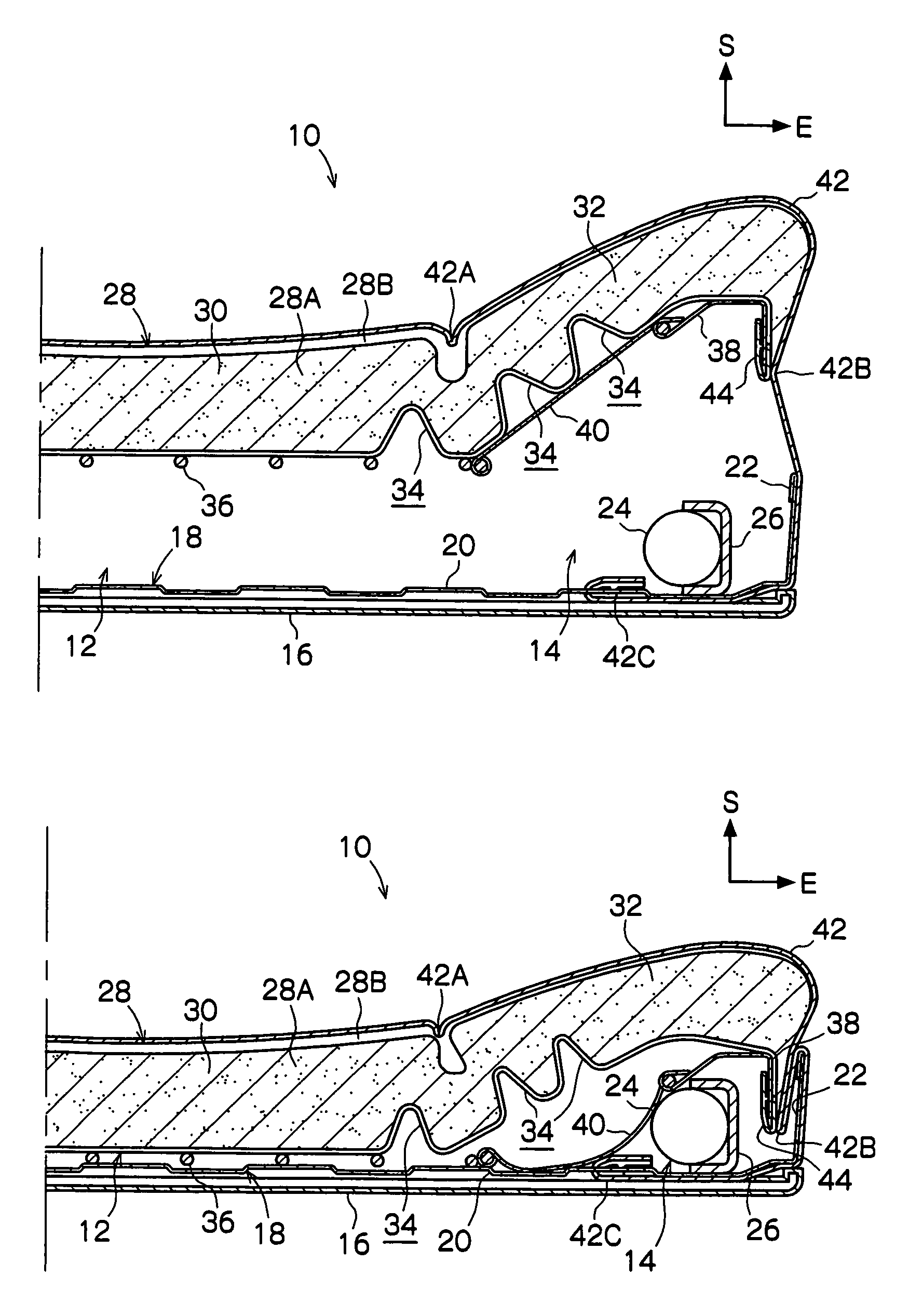
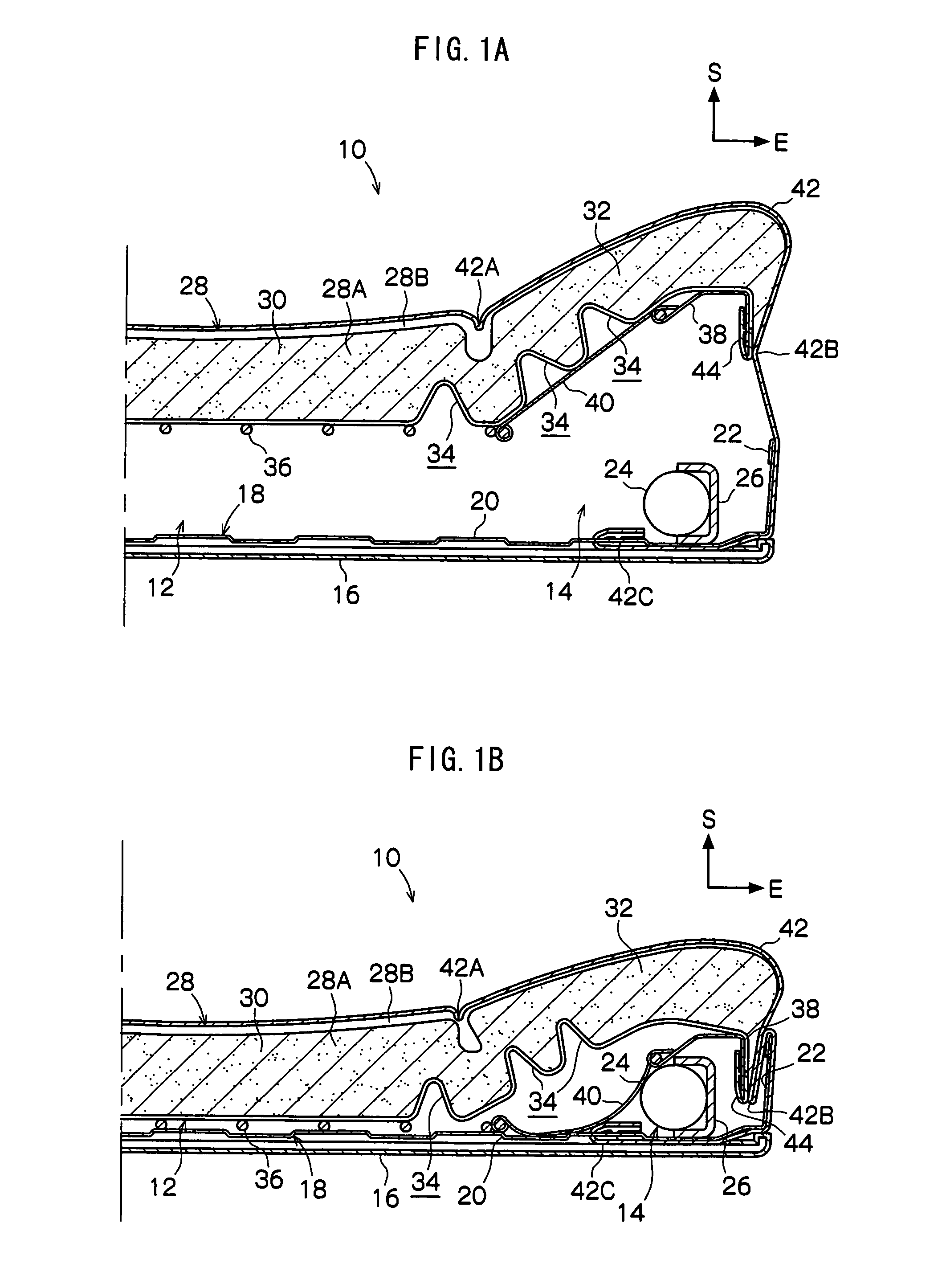
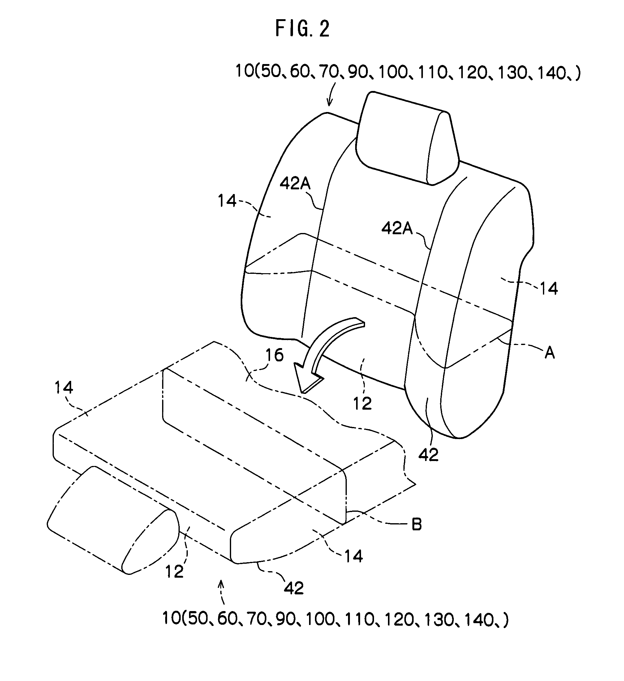
[0066]Main portions of a seat 10, which relates to a first embodiment and which is structured by applying a seat structure and a seat contraction method of the present invention, are shown in a cross-sectional view in FIG. 1A. The seat 10 is shown in FIG. 2 by solid lines in a perspective view seen from an obverse side. Further, in the drawings, the obverse side of the seat 10 is indicated by arrow S, and a lateral direction (transverse direction) outer side of the seat 10 is indicated by arrow E.

[0067]The seat 10 relating to the present embodiment is a seat back of a vehicle. The seat 10 stands substantially vertically from a rear end of a seat cushion of the vehicle (not shown) which is disposed substantially horizontally. As shown by the one-dot chain lines in FIG. 2, the seat 10 is made able to be stowed by being rotated (collapsed forward) around its lower end toward the seat cushion and being superposed on the seat cushion.

[0068]The interior of the late...

second embodiment

[0086][Second Embodiment]

[0087]Main portions of a seat 50, which relates to a second embodiment and which is structured by applying the seat structure and the seat contraction method of the present invention, are shown in a cross-sectional view in FIG. 3A.

[0088]The seat 50 relating to the present embodiment is substantially the same structure as the above-described first embodiment, but differs with regard to the following points.

[0089]In the seat 50 relating to the present embodiment, the pair of vertical walls 22 are not provided at the wall panel 18.

[0090]The skin 42 covers the seat 50 obverse side surface of the pad center portion 30, the seat 50 obverse side surfaces and lateral direction end surfaces of the pad side portions 32, and the lateral wall 20 of the wall panel 18. The skin 42 is not fixed to the movable plates 38. The final ends 42C of the skin 42 are connected to one ends (the seat 50 lateral direction outer side ends) of tension coil springs 52 (rubber or the like ...

third embodiment

[0095][Third Embodiment]

[0096]Main portions of a seat 60, which relates to a third embodiment and which is structured by applying the seat structure and the seat contraction method of the present invention, are shown in a cross-sectional view in FIG. 4A.

[0097]The seat 60 relating to the present embodiment is substantially the same structure as the above-described first embodiment, but differs with regard to the following points.

[0098]In the seat 60 relating to the present embodiment, the pair of vertical walls 22 are not provided at the wall panel 18.

[0099]The movable plate 38 is extended to the spring 36, and the cotton cloth 40 is not provided. The movable plate 38 functions as the supporting member and supports the concave portion 34 formation portion of the pad side portion 32 from the seat 60 reverse side.

[0100]The skin 42 covers the seat 60 obverse side surface of the pad center portion 30, the seat 60 obverse side surfaces and lateral direction end surfaces of the pad side po...


PUM


Abstract

When a seat (10) is to be stowed, a seat pad (28) is moved toward a seat (10) reverse side, pad side portions (32) are rotated toward the seat (10) reverse side with respect to a pad center portion (30), and a center portion (12) and side portions (14) of the seat (10) are contracted. Here, interlockingly with contraction of the side portions (14), a skin (42) is bent and folded in at portions covering distal ends of vertical walls (22) of a wall panel (18) and at second fixing portions (42B). Due thereto, slack of the skin (42) at seat (10) lateral direction end surfaces can be taken in.

Description

TECHNICAL FIELD[0001]The present invention relates to a seat structure and a seat contraction method in which a contracting portion of a seat end portion is made to be contractible.BACKGROUND TECHNOLOGY[0002]As a seat structure, there are those in which, at a seat cushion, the left and right seat side portions are made to be movable to a high position and a low position with respect to a central ceiling plate portion (refer to, for example, Patent Document 1).[0003]In this seat structure, a seat pad within the seat side portion is covered by a seat cover.[0004]However, in this seat structure, when the seat side portions are moved to the low position with respect to the ceiling plate portion, slack arises at the seat cover at the seat cushion end surfaces.[0005][Patent Document 1] Japanese Patent Application Laid-Open (JP-A) No. 2000-316663DISCLOSURE OF THE INVENTION[0006]In view of the aforementioned, an object of the present invention is to provide a seat structure and a seat contr...

Claims


Application Information

Patent Timeline
Patent Type & Authority Patents(United States)
IPC IPC(8): A47C7/14
CPCB60N2/20B60N2/30B60N2/449B60N2/5816B60N2/986B60N2/99
Inventor YAMADAKOBAYASHI, HIDEKITOKAI, TAKESHIMORI, MASAKIONODA, KEISUKEITOU, MAKOTO
Owner TOYOTA JIDOSHA KK
Why Eureka
Try Eureka