Unlock instant, AI-driven research and patent intelligence for your innovation.

Optical position detection apparatus and display apparatus having position detection function

a position detection and display device technology, applied in the direction of instruments, measurement devices, computing, etc., can solve the problems of low environmental resistance, large error, and difficulty in achieving the effect of light reflected from the outer periphery side portions of the light guide plate, and achieve low cost and low power consumption. , the effect of accurate position detection

Active Publication Date: 2012-09-04
COLUMBIA PEAK VENTURES LLC
View PDF4 Cites 13 Cited by
  • Summary
  • Abstract
  • Description
  • Claims
  • Application Information

AI Technical Summary

Benefits of technology

[0010]An advantage of some aspects of the present invention is to provide an optical position detection apparatus and a display apparatus having a position detection function that is provided with the optical position detection apparatus, which can accurately perform position detection even in the case where a position detection method using the intensity distribution of the position detection light formed by the light guide plate is adopted.
[0011]According to an aspect of the invention, there is provided an optical position detection apparatus for optically detecting the position of a target object in a detection area, which includes position detection light sources that emit position detection light irradiated onto the target object; alight guide plate that receives the position detection light therein and emits the received position detection light onto the detection area to form an intensity distribution of a light emission quantity of the position detection light in the detection area; a light detector having light receiving portions arranged toward the detection area to receive the position detection light that is reflected by the target object; and a signal processing portion that detects the position of the target object based on the intensity distribution of the light emission quantity in the detection area, wherein the light guide plate is configured so that light incident portions for receiving the position detection light and side portions except for the light incident portions are provided on the outer periphery side portions when the light guide plate is seen in a plan view, a light emission surface that emits the position detection light incident from the light incident portions toward the detection area is provided on a plane portion when the light guide plate is seen in a plan view, and at least a portion of the side portions is an anti-reflection surface that prevents reflection of the position detection light in the light guide plate.
[0012]According to the aspect of the invention, if the position detection light that is emitted from a light emission surface of the light guide plate is reflected by a target object that is arranged on the emission side of the light guide plate, the reflected light is detected by the light detector. Here, if there is a predetermined correlation between the intensity of the position detection light in the detection area and a distance from the position detection light source, the position of the target object can be detected from a light receiving intensity that is obtained through the light detector. Accordingly, it is not necessary to arrange a plurality of optical devices along the detection area, and thus a position detection apparatus with low cost and with low power consumption can be configured. Here, in the aspect of the invention, in the outer periphery side portions of the light guide plate, at least a portion of the side portions except for the light incident portions is the anti-reflection surface. Accordingly, the light from the position detection light sources directly reach the area that is spaced apart from the position detection light sources, but by only this, it is difficult for the light reflected from the outer periphery side portions of the light guide plate to reach the area. Accordingly, it can be avoided that the light emission intensity of the position detection light emitted from the area that is spaced apart from the light detection light sources becomes heightened in comparison to that of other areas. In the aspect of the invention, even in the case where the position detection method using the intensity distribution of the position detection light formed by the light guide plate is adopted, the position detection light is emitted from the light guide plate with an appropriate intensity distribution, and thus the position detection can be accurately performed.

Problems solved by technology

The ultrasonic type or the capacitive type has a high response speed, but has a low environmental resistance.
However, optical position detection apparatuses as described in JP-A-2004-295644 and JP-A-2004-303172 require light sources or light detectors near the display screen, the number of which corresponds to the resolution of position coordinates that should be detected, and thus are high-cost.
However, the optical position detection apparatus as illustrated in FIGS. 10A and 10B has a problem that when the position of the finger and so on is actually detected by the optical position detection apparatus, a large error may occur.
Accordingly, the light from the position detection light sources directly reach the area that is spaced apart from the position detection light sources, but by only this, it is difficult for the light reflected from the outer periphery side portions of the light guide plate to reach the area.
Accordingly, the light from the position detection light sources directly reach the area that is spaced apart from the position detection light sources, but it is difficult for the light reflected from the outer periphery portions of the light guide plate to reach the area.

Method used


Image

  • Optical position detection apparatus and display apparatus having position detection function
  • Optical position detection apparatus and display apparatus having position detection function
  • Optical position detection apparatus and display apparatus having position detection function

Examples


modified example 1

of Display Apparatus 100 Having Position Detection Function

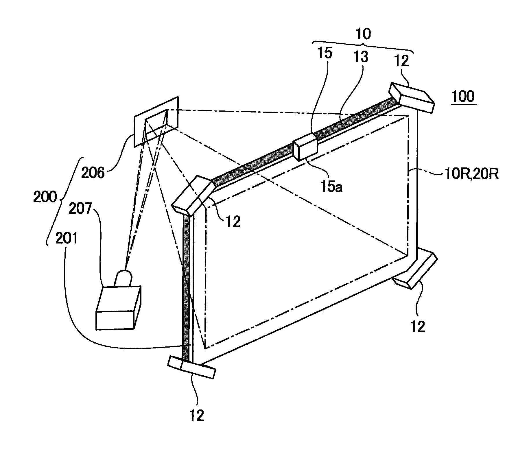
[0092]FIG. 5 and FIG. 6 are an exploded perspective view of the optical position detection apparatus 10 and the display apparatus 100 having position detection function according to the modified example 1 of the invention, and an explanatory view illustrating a cross-sectional configuration thereof. In the display apparatus 100 having position detection function in this embodiment, since the configuration of the optical position detection apparatus 10 is the same as that of the above-described embodiment, the common parts are designated with the same reference symbols and the explanation thereof will be omitted.

[0093]The display apparatus 100 having position detection function shown in FIGS. 5 and 6 includes the optical position detection apparatus 10 and the image generation apparatus 200, and the optical position detection apparatus 10 includes the position detection light source 12 emitting position detection light, the l...

modified example 2

of Display Apparatus 100 Having Position Detection Function

[0094]FIGS. 7 and 8 are explanatory views of the optical position detection apparatus 10 and the display apparatus 100 having position detection function according to the modified example 2 of the invention. FIG. 7 and FIG. 8 are an exploded perspective view of the optical position detection apparatus 10 and the display apparatus 100 having position detection function according to the modified example 2 of the invention, and an explanatory view illustrating a cross-sectional configuration thereof, respectively. In the display apparatus 100 having position detection function in this embodiment, since the configuration of the optical position detection apparatus 10 is the same as that of the above-described embodiment, the common parts are designated with the same reference symbols and the explanation thereof will be omitted.

[0095]The display apparatus 100 having position detection function shown in FIGS. 7 and 8 includes the ...


PUM


Abstract

An apparatus for optically detecting an object position includes: position detection light sources irradiating light onto the object; a light guide plate receiving the light and emitting it onto a detection area to form an intensity distribution in the detection area; a light detector having light receiving portions receiving the light reflected by the object; and a signal processing portion detecting the object position based on the intensity distribution, wherein light incident portions receiving the light and side portions except for the light incident portions are provided on outer periphery side portions of the light guide plate, a light emission surface emitting the light incident from the light incident portions toward the detection area is provided on a plane portion of the light guide plate, and at least a portion of the side portions is an anti-reflection surface.

Description

[0001]This application claims priority to Japanese Patent Application Nos. 2009-178777 filed Jul. 31, 2009 and 2010-060335 filed Mar. 17, 2010 which are hereby expressly incorporated by reference herein in their entireties.BACKGROUND[0002]1. Technical Field[0003]The present invention relates to an optical position detection apparatus and a display apparatus having a position detection function that is provided with the optical position detection apparatus.[0004]2. Related Art[0005]In an electronic appliance such as a portable phone, car navigation system, personal computer, ticket machine, bank terminal, or the like, a display apparatus having a position detection function, in which a touch panel is arranged on the front surface of an image generation apparatus such as a liquid crystal apparatus, has been used recently. In a display apparatus having the position detection function as described above, an input of information is performed while an image displayed on the image generati...

Claims


Application Information

Patent Timeline
Patent Type & Authority Patents(United States)
IPC IPC(8): G01B11/14
CPCG01B11/14G06F3/0428
Inventor KIYOSE, KANECHIKA
Owner COLUMBIA PEAK VENTURES LLC