Bicycle generator hub

a generator hub and bicycle technology, applied in the field of hubs, can solve the problems of troublesome task of running (arranging) a wire, and troublesome positioning of the generator hub in this manner, and achieve the effect of convenient positioning and efficient task of running a wir

Active Publication Date: 2013-03-26
SHIMANO INC +1
View PDF33 Cites 27 Cited by
  • Summary
  • Abstract
  • Description
  • Claims
  • Application Information

AI Technical Summary

Benefits of technology

[0007]One object of the present invention is to provide a generator hub that enables the task of running a wire to be accomplished more efficiently when the generator hub is mounted to a frame.
[0009]When this generator hub is mounted to the frame of the bicycle, the positioning device provided on the hub shaft positions the connector about the hub shaft in a rotational direction while the hub shaft is mounted to the frame. Thus, when the hub shaft is mounted to a frame of a bicycle, the connector can be positioned in a rotational direction of the hub shaft and thereby positioned with respect to the frame. Consequently, it is not necessary to position the generator hub every time the generator hub is mounted. As a result, the task of running a wire can be accomplished more efficiently.
[0010]A generator hub according to a second aspect is the generator hub according to the first aspect, wherein the positioning device includes a protrusion extending from the hub shaft to engage with a fork end of the frame. With this aspect, the connector can be positioned easily by engaging the protruding part with the end portion of the frame.
[0012]A generator hub according to a fourth aspect is the generator hub according to any one of the first to third aspects, wherein the hub shaft is further provided with a quick-release mechanism for easy attachment and detachment of the hub shaft to and from the frame. When the generator hub is equipped with a quick-release mechanism, the generator hub can be attached to and detached from the bicycle frame more easily. Thus, the effect of the positioning device is more apparent in a generator hub equipped with a quick-release mechanism.

Problems solved by technology

It is troublesome to position the generator hub in this manner every time the generator hub is mounted to a bicycle frame.
In short, the task of running (arranging) a wire is troublesome with a generator hub according to the prior art.

Method used


Image

  • Bicycle generator hub
  • Bicycle generator hub
  • Bicycle generator hub

Examples


Embodiment Construction

[0021]Selected embodiments of the present invention will now be explained with reference to the drawings. It will be apparent to those skilled in the art from this disclosure that the following descriptions of the embodiments of the present invention are provided for illustration only and not for the purpose of limiting the invention as defined by the appended claims and their equivalents.

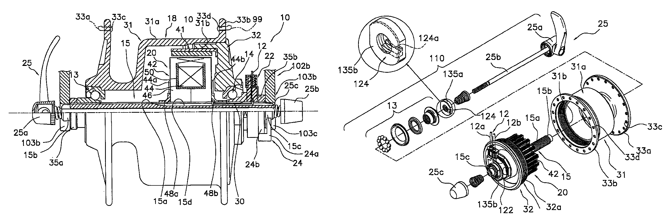
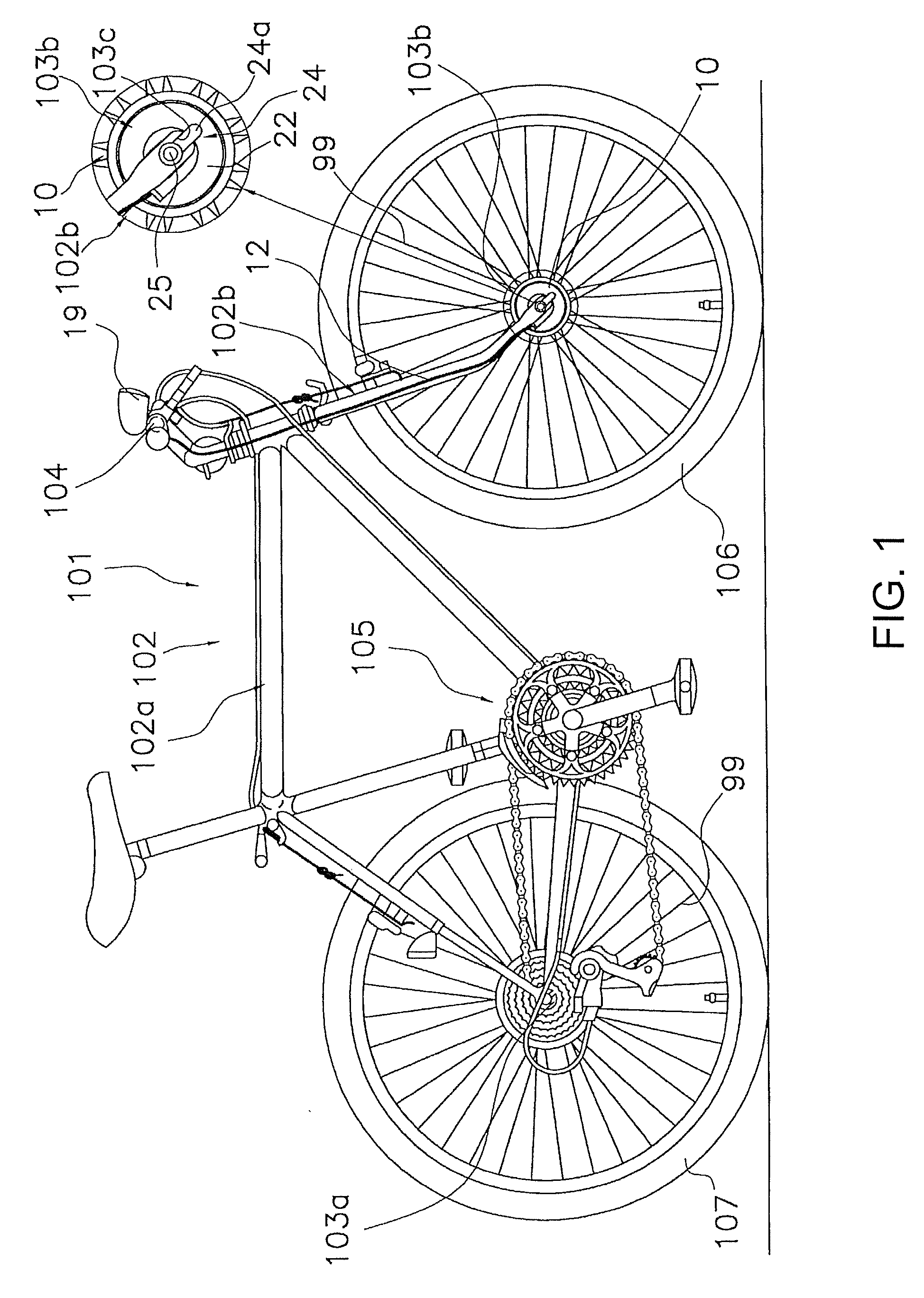
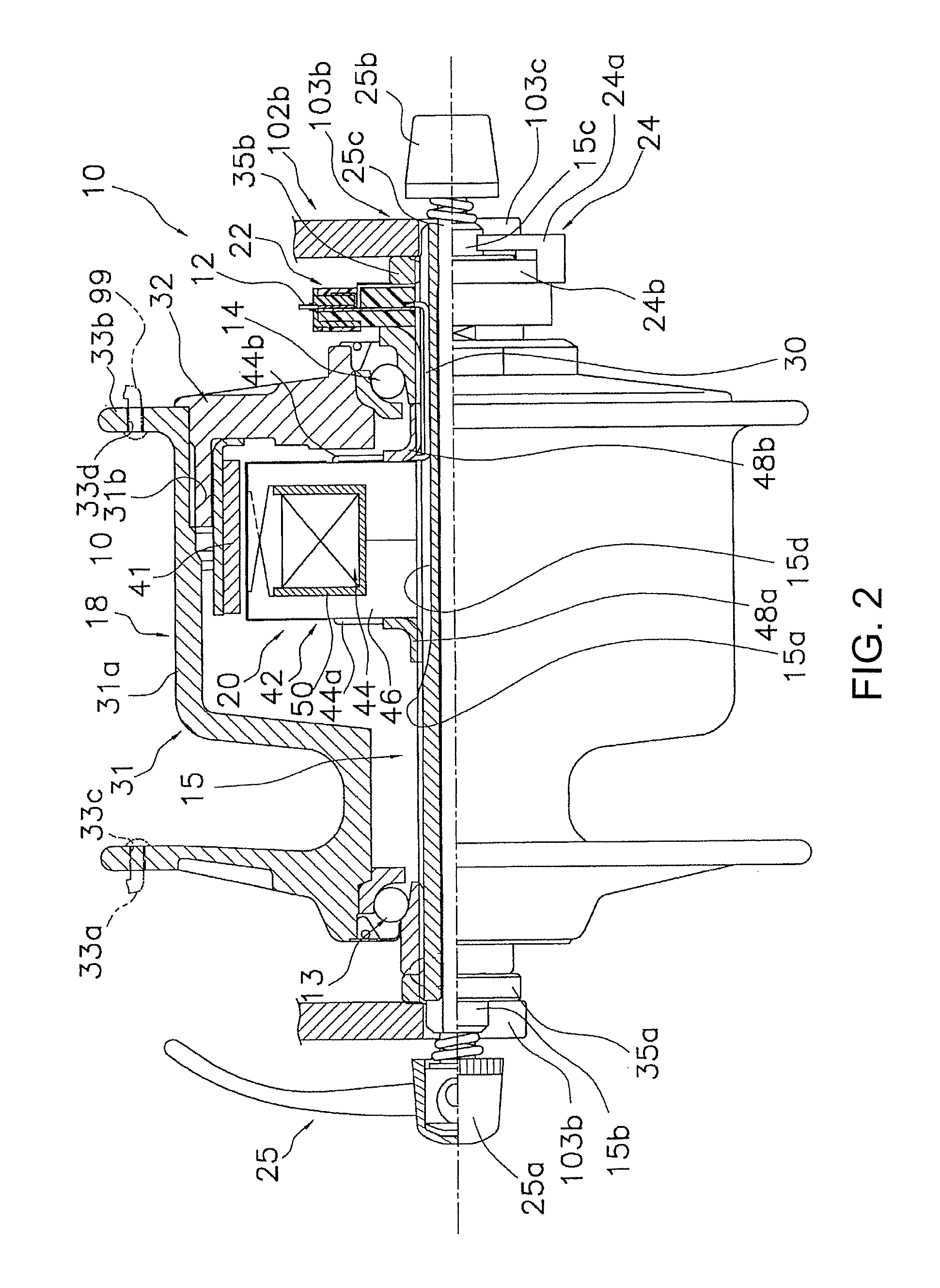
[0022]Referring initially to FIG. 1, a bicycle 101 is illustrated with a generator hub 10 in accordance with a first embodiment. The bicycle 101 mainly includes a frame 102, a handlebar unit 104, a drive section 105, a front wheel 106 and a rear wheel 107. The drive section 105 includes a chain, pedals, etc. The front wheel 106 has a plurality of spokes 99. The rear wheel 107 also has a plurality of spokes 99. The frame 102 has a frame body 102a and a front fork 102b. The front fork 102b is mounted to a front portion of the frame body 102a such that it can pivot freely about a diagonal axis. The ha...


PUM


Abstract

A generator hub is basically provided with a hub shaft, a generator mechanism, a connector and a positioning device. The generator mechanism is provided on the hub shaft. The connector is disposed on the hub shaft and electrically connected to the generator mechanism. The positioning device is disposed on the hub shaft, the positioning device being configured and arranged to position the connector with respect to a frame of a bicycle in a rotational direction about the hub shaft.

Description

CROSS-REFERENCE TO RELATED APPLICATIONS[0001]This application claims priority under 35 U.S.C. §119 to Japanese Patent Application No. 2009-132306, filed Jun. 1, 2009. The entire disclosure of Japanese Patent Application No. 2009-132306 is hereby incorporated herein by reference.BACKGROUND OF THE INVENTION[0002]1. Field of the Invention[0003]This invention generally relates to a hub for a wheel. More specifically, the present invention relates to a generator hub that is mounted to a frame of a bicycle.[0004]2. Background Information[0005]Some bicycles are equipped with a generator to power electrical devices on the bicycle. For example, Japanese Laid-Open Patent Publication No. 2004-229418 discloses a conventional generator hub that serves as a hub positioned at a center of a wheel of a bicycle and has an electric generator mechanism. The generator hub has a hub shaft, a generator mechanism provided on the hub shaft, and a connector (electrical connector) that is provided on the hub ...

Claims


Application Information

Patent Timeline
Patent Type & Authority Patents(United States)
IPC IPC(8): H02K7/18B62J6/12
CPCH02K7/1846H02K5/225
Inventor ANDO, YOSHIAKITAKACHI, TAKESHITHIAM, LIM PUAT
Owner SHIMANO INC
Why Eureka
Try Eureka