AI technical title is built by Patsnap AI team. It summarizes the technical point description of the patent document.
a technology of impact tool and tool body, which is applied in the direction of cutting machine, drilling accessories, cutting machines, etc., can solve the problems of wear and tear of the impact tool
Active Publication Date: 2013-07-16
SCHLUMBERGER TECH CORP
View PDF177 Cites 36 Cited by
Summary
Abstract
Description
Claims
Application Information
AI Technical Summary
This helps you quickly interpret patents by identifying the three key elements:
Problems solved by technology
Method used
Benefits of technology
Problems solved by technology
Formation degradation, such as asphalt milling, mining, or excavating, may result in wear on attack tools.
Method used
Image
Click on the blue label to locate the original text in one second.
Reading with bidirectional positioning of images and text.
Examples
Embodiment Construction
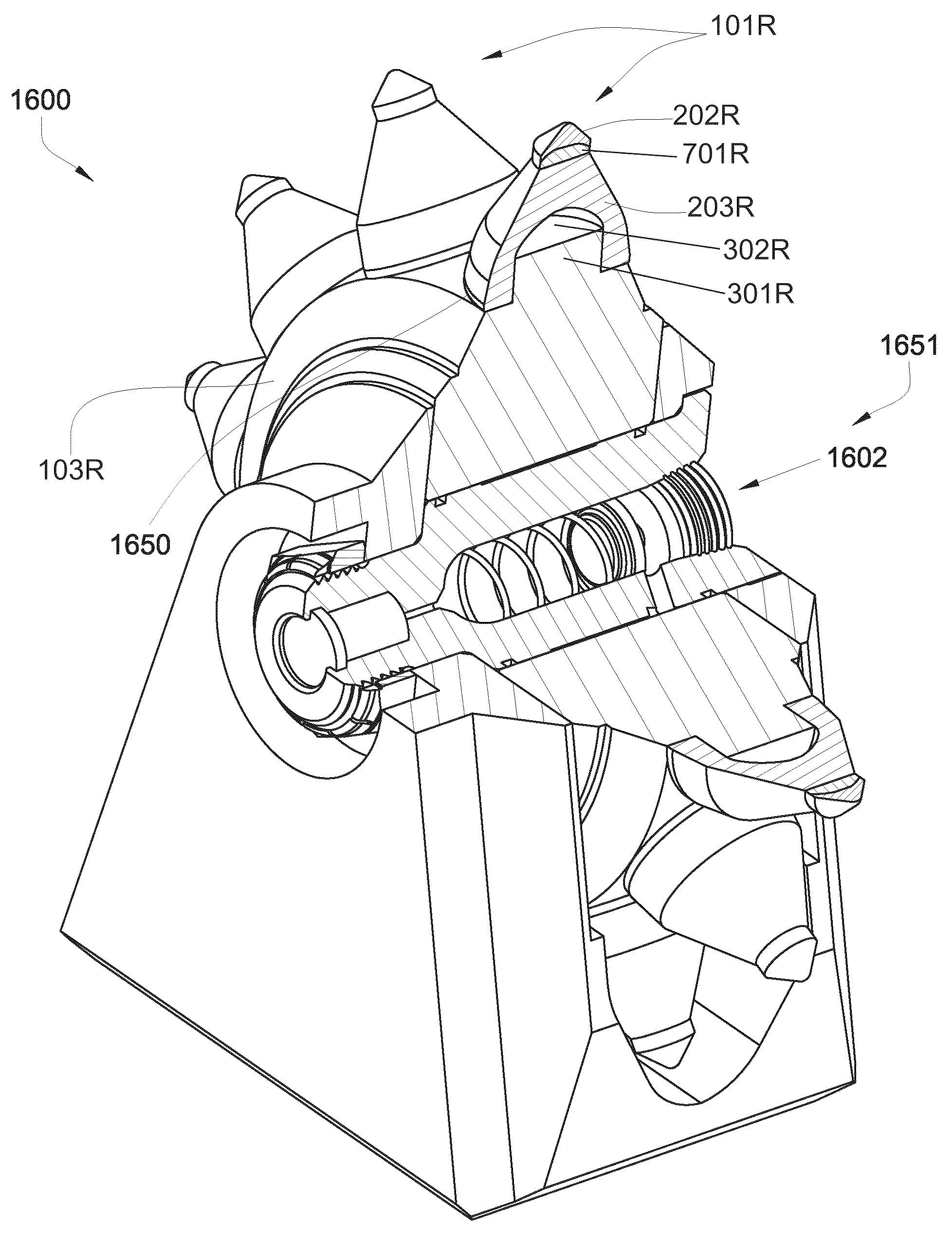
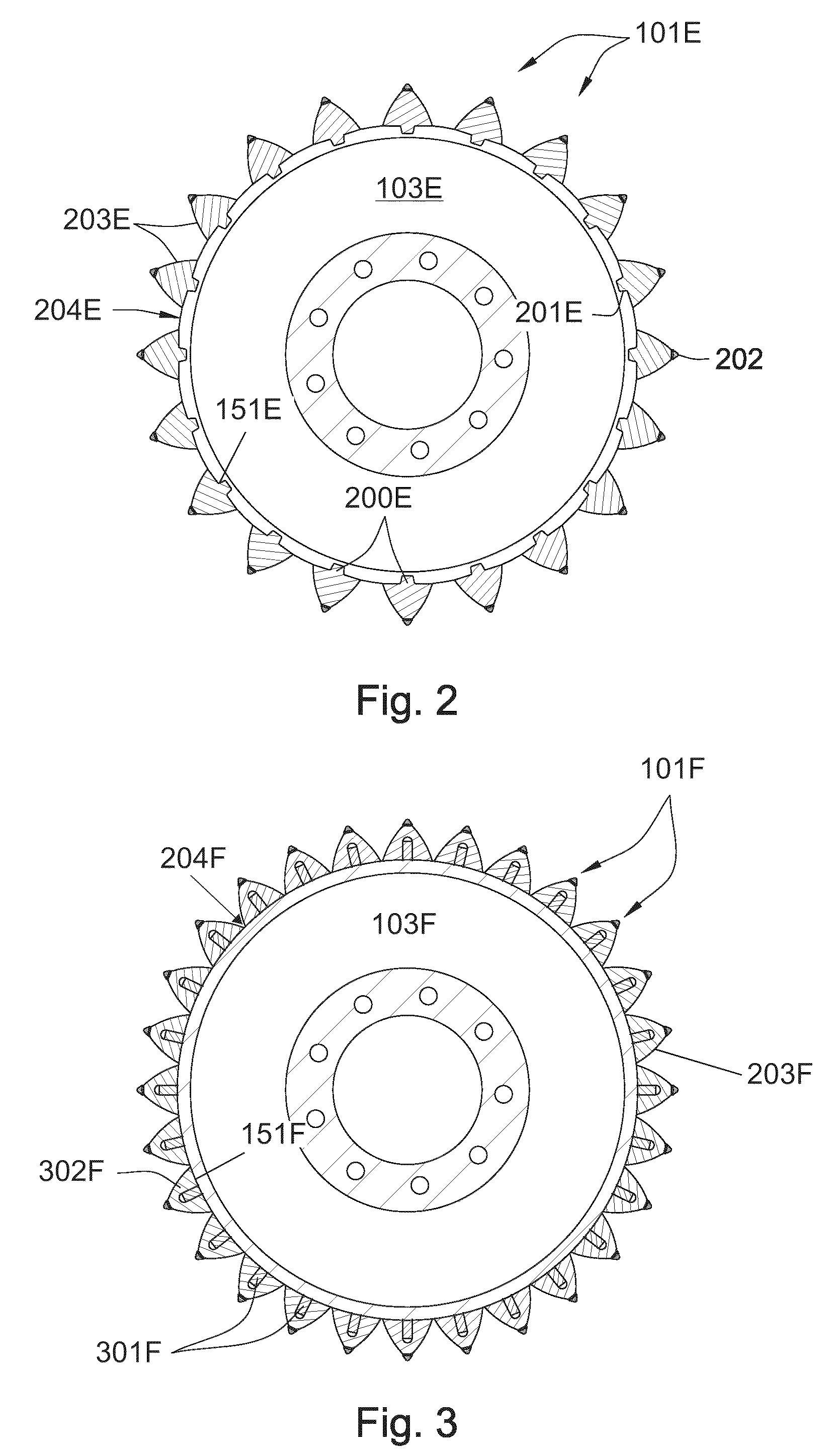
[0045]In accordance with one exemplary embodiment, FIG. 1 is a cross-sectional diagram of a plurality of impact tools 101 attached to a driving mechanism, such as rotating drum 103, which in turn is connected to the underside of a pavement recycling machine 100. The recycling machine 100 may be a cold planer used to degrade man-made formations such as a paved surface 104 prior to the placement of a new layer of pavement. Impact tools 101 may be attached to the driving mechanism which rotates the impact tools 101 into engagement with the formation 104.
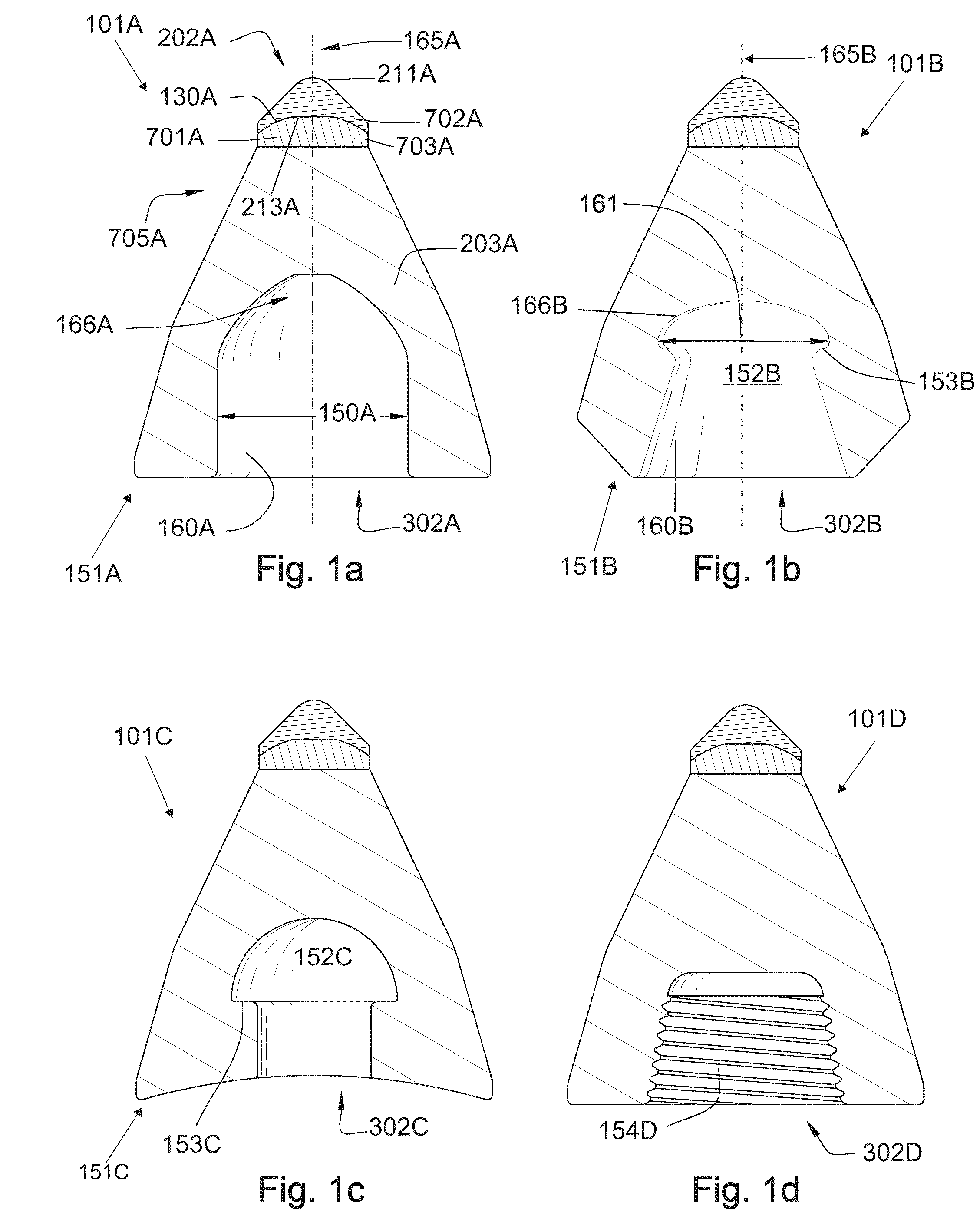
[0046]FIG. 1a is a cross-sectional diagram of an embodiment of an impact tool 101A. The impact tool 101A may comprise an impact tip 202A having an apex 211A and an attachment end 213A opposite the apex, and being formed from a super hard material. The super hard material may comprise diamond, polycrystalline diamond with a binder concentration of 1 to 40 weight percent, cubic boron nitride, refractory metal bonded diamond, silicon bonde...
PUM
Property
Measurement
Unit
diameter
aaaaa
aaaaa
diameter
aaaaa
aaaaa
angle
aaaaa
aaaaa
Abstract
An impact tool for use with a driving mechanism, the impact tool including an impact tip formed from a super hard material and having an apex and an attachment end, with the attachment end being bonded to a cemented metal carbide substrate at a non-planar interface. The cemented metal carbide substrate is bonded in turn to the front end of a cemented metal carbide bolster. The carbide bolster is securable against an outer surface of a driving mechanism through a press fit.
Description
RELATED APPLICATIONS[0001]This application is a continuation-in-part of U.S. patent application Ser. No. 11 / 971,965, filed Jan. 10, 2008, now U.S. Pat. No. 7,648,210, which is a continuation of U.S. patent application Ser. No. 11 / 947,644, filed Nov. 29, 2007, which is a continuation-in-part of U.S. patent application Ser. No. 11 / 844,586, filed Aug. 24, 2007, now U.S. patent application Ser. No. 11 / 844,586 is a continuation-in-part of U.S. patent application Ser. No. 11 / 829,761, filed Jul. 27, 2007, now U.S. Pat. No. 7,722,127. U.S. patent application Ser. No. 11 / 829,761 is a continuation-in-part of U.S. patent application Ser. No. 11 / 773,271, filed Jul. 3, 2007. U.S. patent application Ser. No. 11 / 773,271 is a continuation-in-part of U.S. patent application Ser. No. 11 / 766,903, filed Jun. 22, 2007. U.S. patent application Ser. No. 11 / 766,903 is a continuation of U.S. patent application Ser. No. 11 / 766,865, filed Jun. 22, 2007. U.S. patent application Ser. No. 11 / 766,865 is a continu...
Claims
Application Information
Patent Timeline
Application Date:The date an application was filed.
Publication Date:The date a patent or application was officially published.
First Publication Date:The earliest publication date of a patent with the same application number.
Issue Date:Publication date of the patent grant document.
PCT Entry Date:The Entry date of PCT National Phase.
Estimated Expiry Date:The statutory expiry date of a patent right according to the Patent Law, and it is the longest term of protection that the patent right can achieve without the termination of the patent right due to other reasons(Term extension factor has been taken into account ).
Invalid Date:Actual expiry date is based on effective date or publication date of legal transaction data of invalid patent.
Patent Type & AuthorityPatents(United States)
IPC IPC(8): E21C35/197
CPCE21C35/183E21C35/19
InventorHALLCROCKETT, RONALDDAHLGREN, SCOTTWILDE, TYSON J.

