Rigid tie down

a tie-down and rigid technology, applied in the field of tie-downs, can solve the problems of hardly binding the goods tightly, inconvenience in practical use, time and labor consumption, etc., and achieve the effect of simple configuration

Active Publication Date: 2013-08-13
ZHEJIANG TOPSUN LOGISTIC CONTROL CO LTD
View PDF16 Cites 24 Cited by
  • Summary
  • Abstract
  • Description
  • Claims
  • Application Information

AI Technical Summary

Benefits of technology

[0011]It is therefore an object of the present invention to provide a rigid tie down which has a simple configuration and could bind the goods tightly, so as to address the afore-mentioned problems existing in the prior art.

Problems solved by technology

Although cords are conventionally directly used to bind the goods, they are time and labor consuming and could hardly bind the goods tightly.
However, since the tie down is fixed on the vehicle body and restricted to a certain position, the crowbar should be pulled out and inserted into another crowbar hole after the belt axis is driven to rotate by a certain angle through turning the crowbar during operation, and thus the belt axis could continue to rotate.
Meanwhile, the crowbar has to be repeatedly pulled out and inserted, bringing inconvenience in practical use.
By using such a control device, some convenience is provided when the goods are bound, but the action is quite slow during untying the goods.
It could be understood that the current tie down is labor and time consuming during operation, and has a low binding efficiency or a low untying speed.
Moreover, since the crowbar are continually pulled out and inserted, the finger(s) or other parts of the operator tend to be hurt.
The rapid-turn manual tie down device mentioned above has a relatively complicated configuration and could only turn in one way with the ratchet wheel in cooperation with the pawl.
In addition, the rapid-turn manual tie down device has low safety and reliability during operation.
The binding strap of said device could not be loosened quickly, which impairs the efficiency thereof.
Said device further occupies a larger space.

Method used


Image

  • Rigid tie down
  • Rigid tie down
  • Rigid tie down

Examples


Embodiment Construction

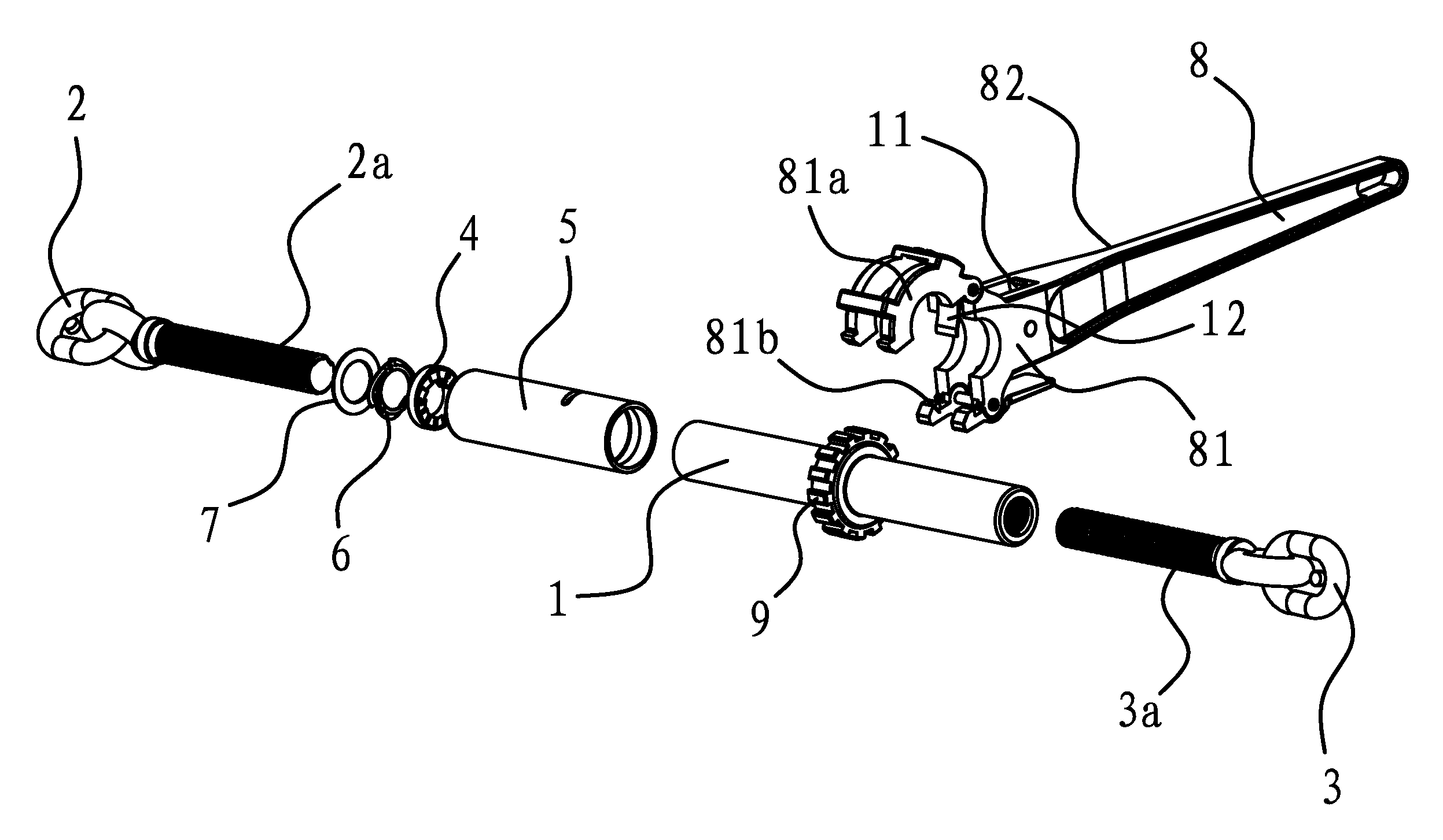
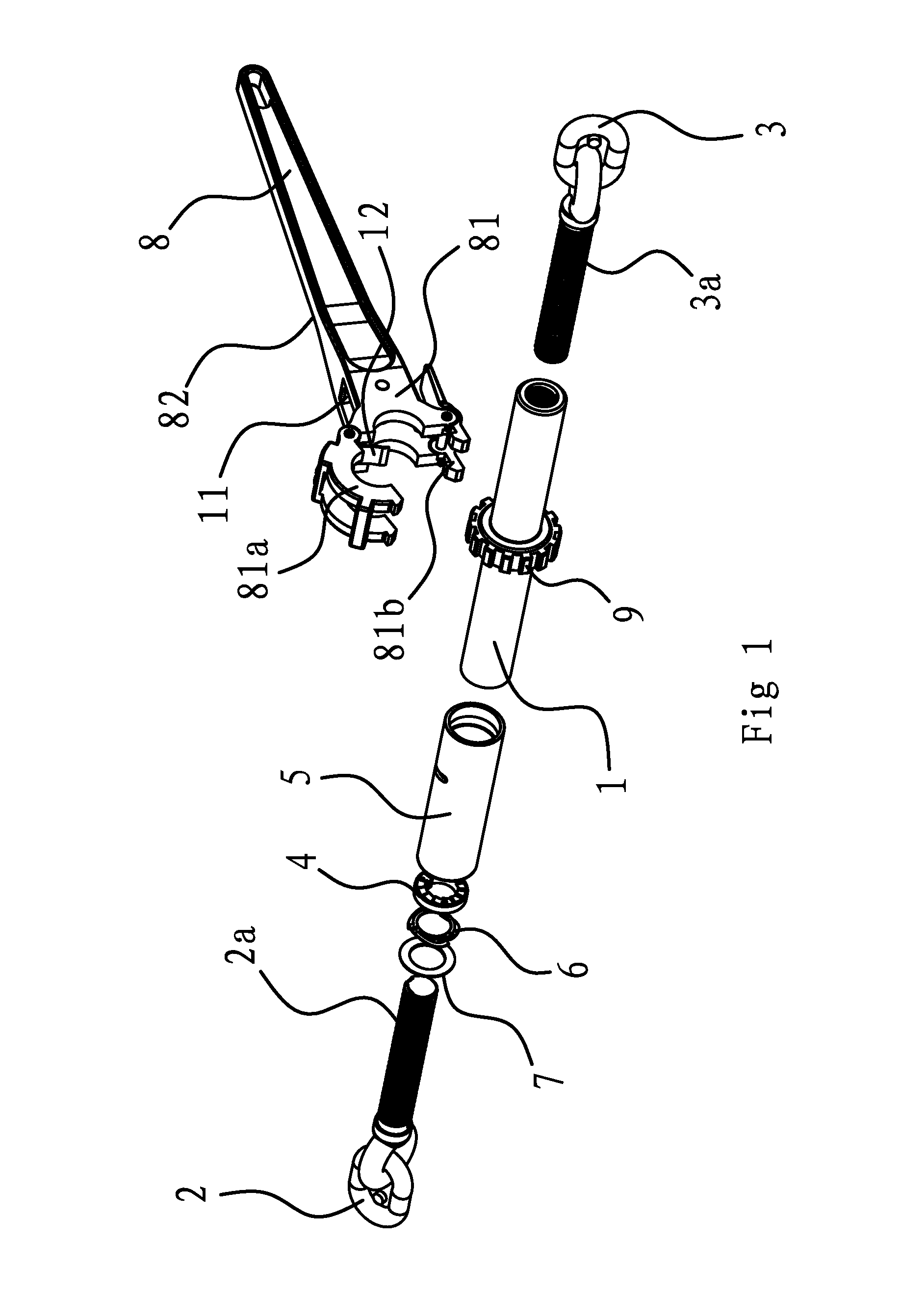
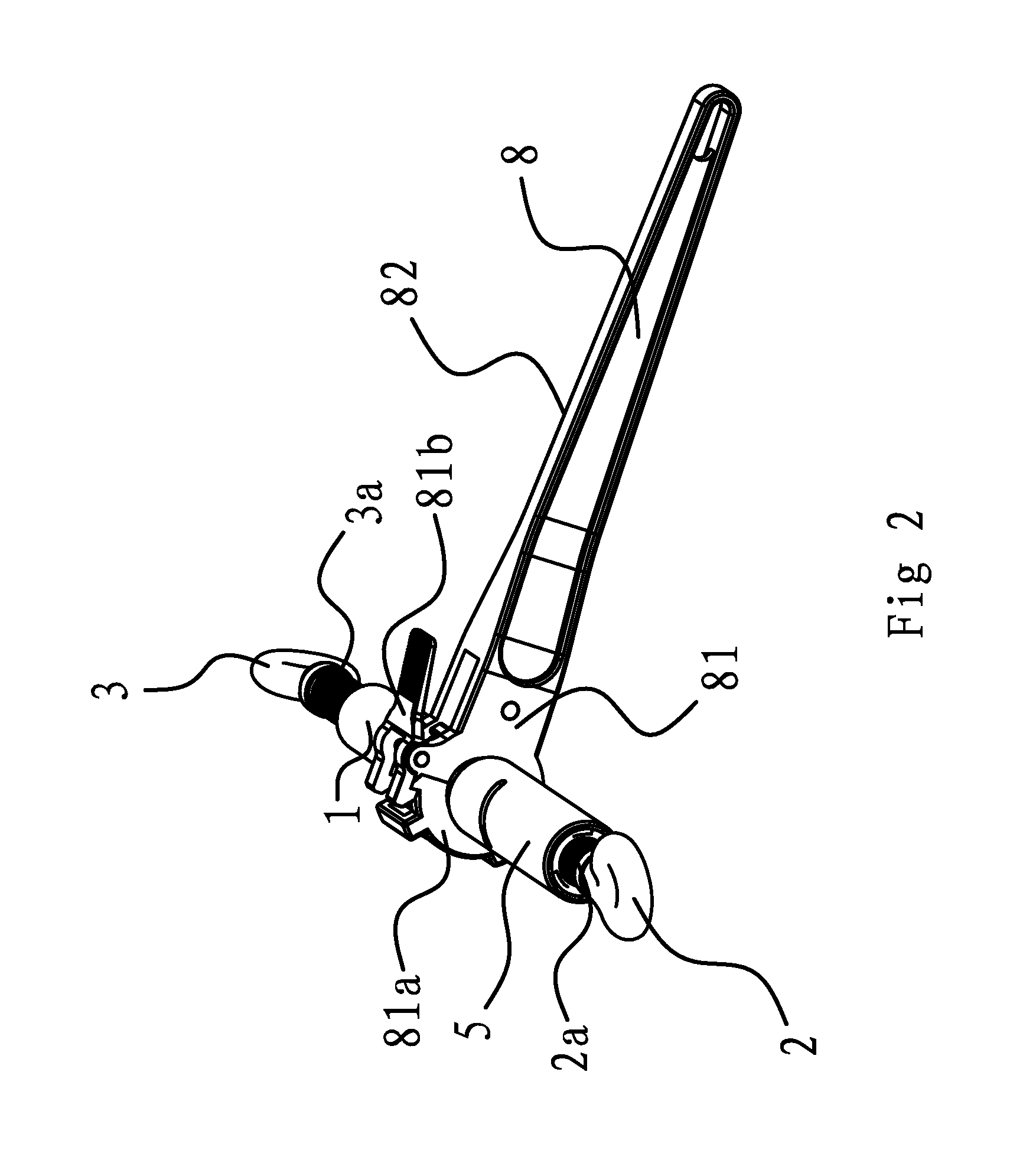
[0055]As shown in FIGS. 1 and 2, the rigid tie down of the invention includes a body 1, a first hook 2 and a second hook 3. The body 1 has a cylindrical shape. The first hook 2 has a first screw 2a integrated therewith. The second hook 3 has a second screw 3a integrated therewith. The first screw 2a of the first hook 2 is threadedly connected with one end of the body 1. The second screw 3a of the second hook 3 is threadedly connected with the other end of the body 1. In other words, both ends of the body 1 are respectively covered on and threadedly connected with the first screw 2a and the second screw 3a. The threads of the first screw 2a of the first hook 2 are reverse to those of the second screw 3a of the second hook 3. A handle 8 is connected with the body 1.

[0056]As shown in FIGS. 3, 4 and 5, a locking mechanism is provided between the first screw 2a of the first hook 2 and the body 1 to lock or separate them. The locking mechanism includes a first meshing element 1a at the en...


PUM

PropertyMeasurementUnit
elasticaaaaaaaaaa
elastic forceaaaaaaaaaa
flexibleaaaaaaaaaa

Abstract

The present invention discloses a rigid tie down in the field of mechanics, which addresses the problems of the existing tie downs, for example, they occupy a large space and have a low binding efficiency. The rigid tie down comprises a body, a first hook and a second hook provided on both ends of the body, and a handle connected to the body. The body has a cylindrical shape. The first hook has a first screw thereon, and the second hook has a second screw thereon. The first screw is threadedly connected with one end of the body, and the second screw is threadedly connected with the other end of the body. The direction of the threads of the first screw is reverse to that of the second screw. The rigid tie down could be operated in a convenient manner, have a high binding efficiency and occupy a small space.

Description

BACKGROUND OF THE INVENTION[0001]1. Field of Invention[0002]The present invention relates to a tied down, in particular, to a rigid tie down in the field of mechanics.[0003]2. Related Art[0004]Goods usually desire to be bound during transportation by vehicles to prevent the goods falling off or colliding with each other to cause loss or damage during travel of the vehicles. Although cords are conventionally directly used to bind the goods, they are time and labor consuming and could hardly bind the goods tightly. The tie down is an advanced binding means, the use of which is very popular among drivers due to convenience and safety.[0005]The conventional tie down is made of a support, a belt axis and a binding strap. The belt axis is connected to the support and rotatable. The binding strap is wound around the belt axis. A crowbar hole is set on the outer end of the belt axis beyond the support.[0006]In order for the goods to be bound, the crowbar is inserted into the crowbar hole to...

Claims


Application Information

Patent Timeline
Patent Type & Authority Patents(United States)
IPC IPC(8): B66F3/00B21F9/00
CPCB25B13/48B25B13/50F16G3/006Y10T403/293Y10T403/291
Inventor RUAN, BUQIN
Owner ZHEJIANG TOPSUN LOGISTIC CONTROL CO LTD
Why Eureka
Try Eureka