Capacitor arrangement and method for producing a capacitor arrangement

a capacitor and capacitor technology, applied in the manufacture of printed circuits, basic electric elements, electric devices, etc., can solve the problem of low parasitic inductance between the power elements and the capacitor, and achieve the effect of preventing a great influence of temperature on the capacitor and reducing the temperature influence on the capacitor

Inactive Publication Date: 2014-02-11
MTU AERO ENGINES GMBH
View PDF14 Cites 2 Cited by
  • Summary
  • Abstract
  • Description
  • Claims
  • Application Information

AI Technical Summary

Benefits of technology

[0008]The present invention is based on the finding that a capacitor can be applied to a substrate of a power module through the use of specially shaped capacitor terminal plates without any loss of lifetime. Damage to the capacitor due to high temperature stress due to the soldering process can be prevented according to the invention. In this way it is possible to ensure capacitor availability after the manufacturing process.
[0026]This method may comprise a step of creating soldered joints which are embodied to connect at least a few of the protrusions on the first terminal plate to the first power rail and to connect at least a few of the protrusions on the second terminal plate to the second power rail. In this way the capacitor arranged between the terminal plates can be connected to the power rails, such that a temperature influence on the capacitor can again be minimized.

Problems solved by technology

This leads to a low parasitic inductance between the power elements and the capacitor.

Method used


Image

  • Capacitor arrangement and method for producing a capacitor arrangement
  • Capacitor arrangement and method for producing a capacitor arrangement
  • Capacitor arrangement and method for producing a capacitor arrangement

Examples


Embodiment Construction

[0036]In the following description of the preferred exemplary embodiments of the present invention, the same or similar reference numerals are used for the similarly acting elements depicted in the various drawings, thereby omitting a repeated description of these elements.

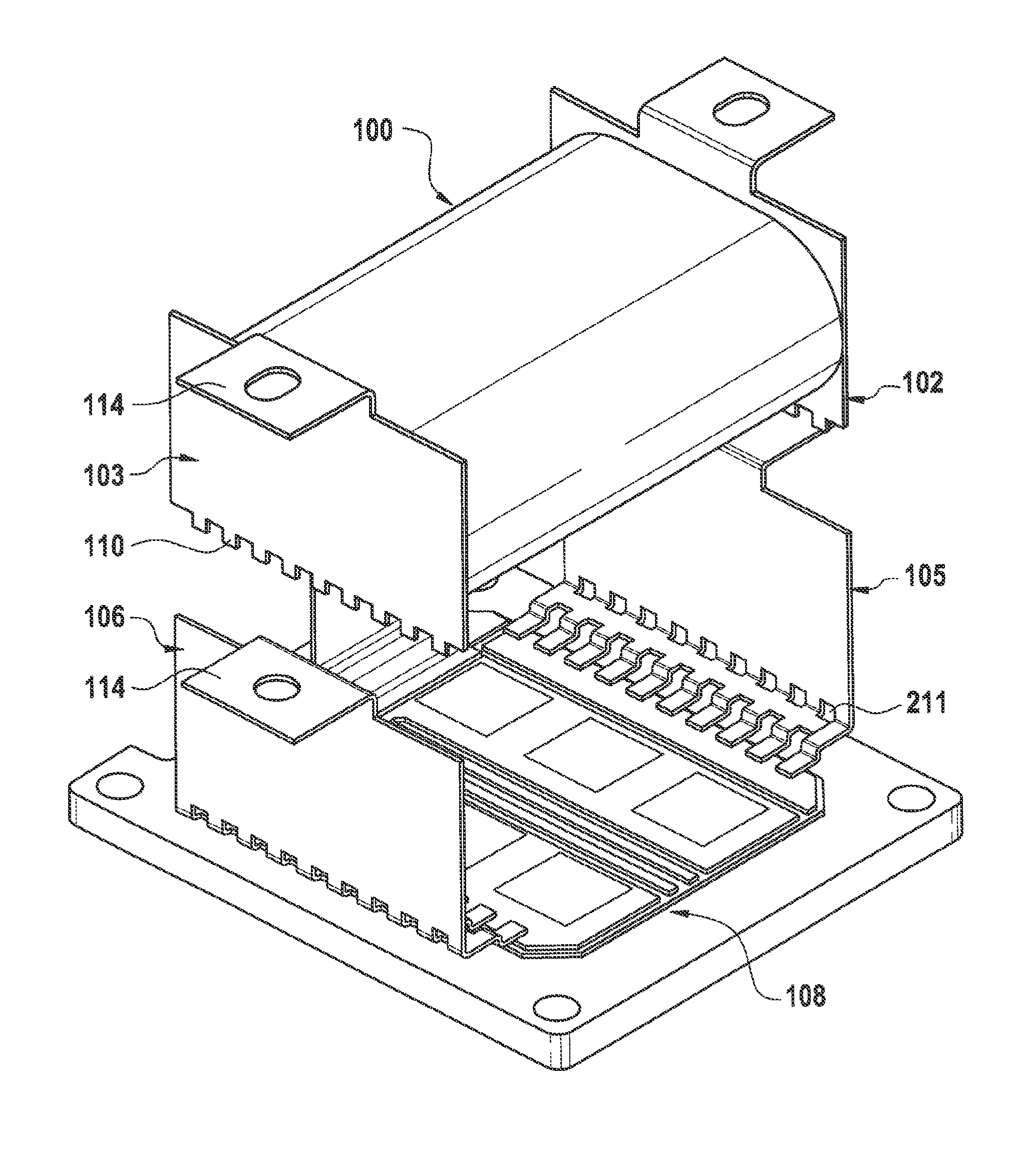
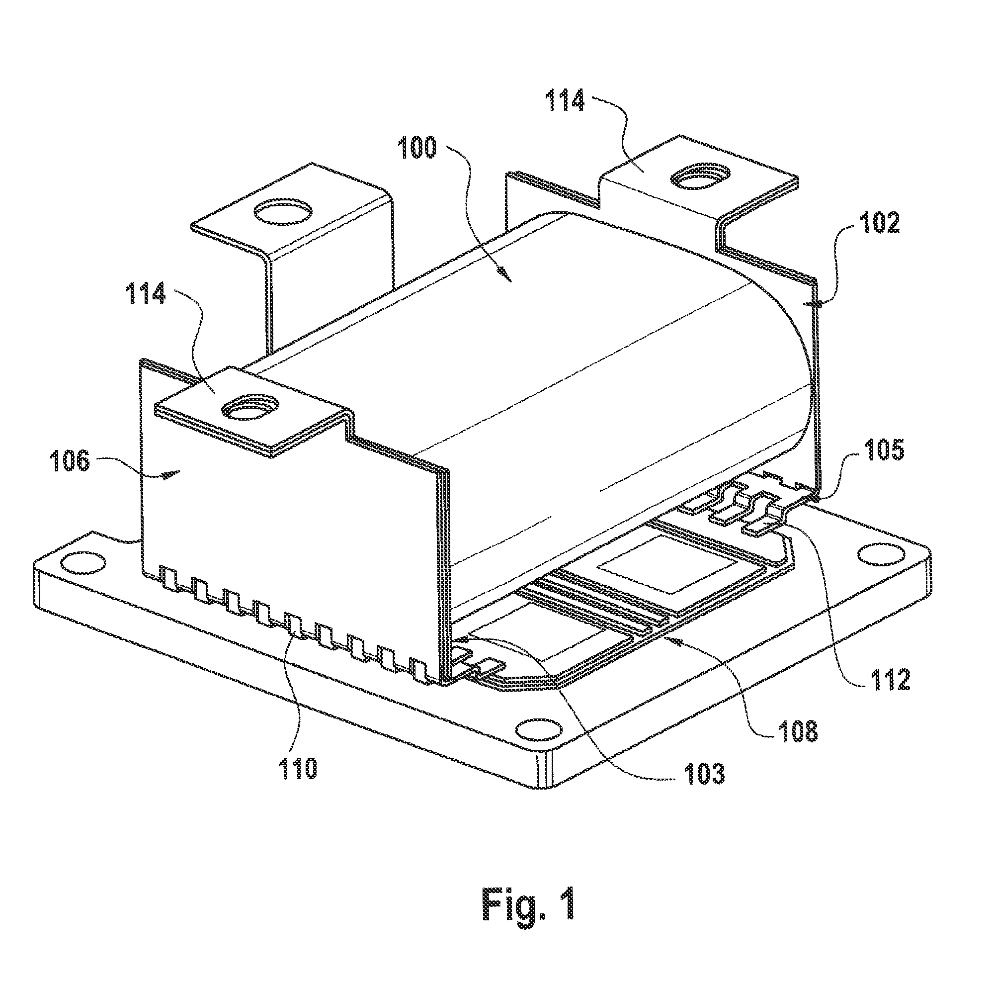
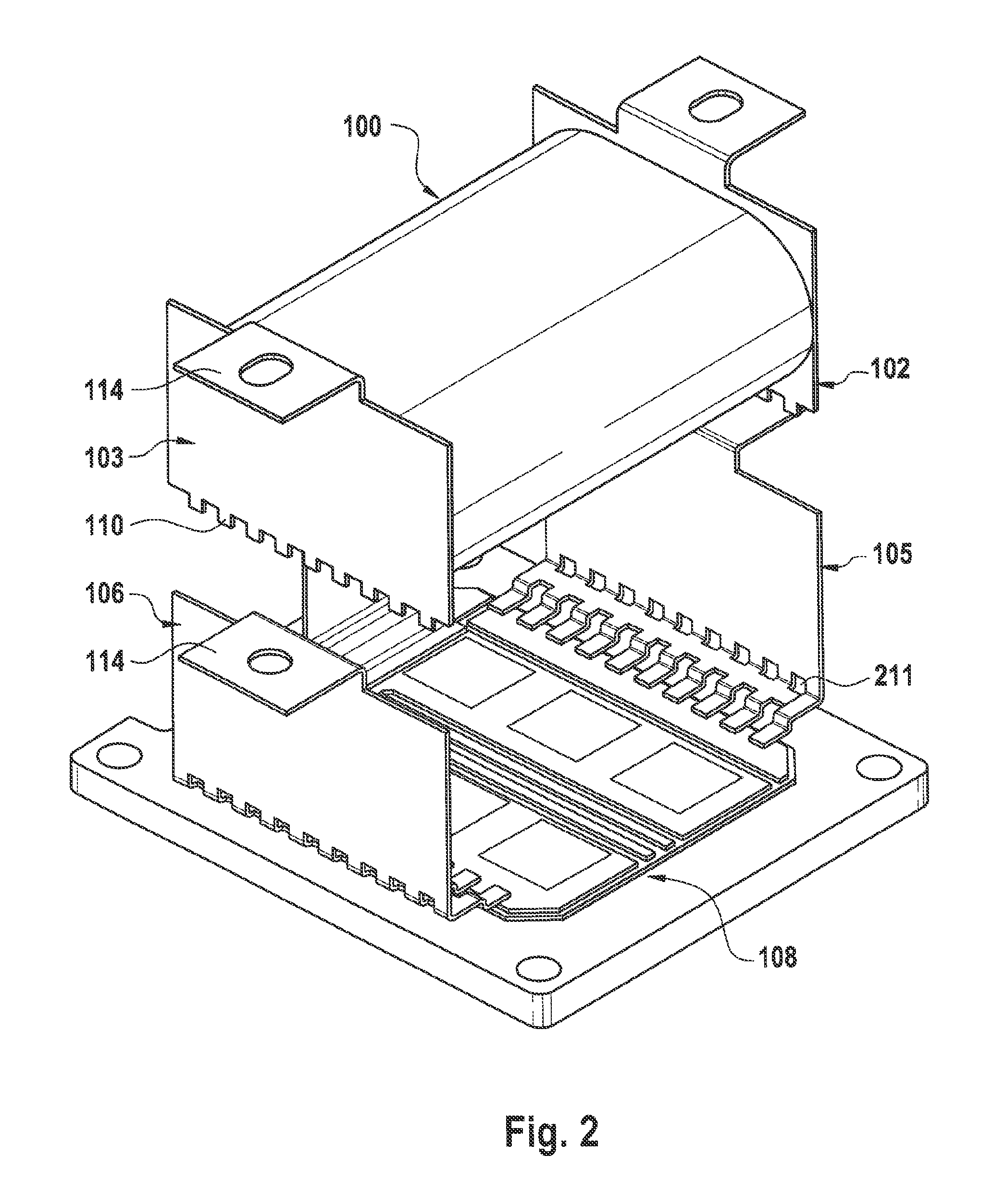
[0037]FIG. 1 shows a capacitor arrangement according to an exemplary embodiment of the present invention. This shows in particular a final modular diagram without a housing. The capacitor arrangement has a capacitor 100, a first terminal plate 102 and a second terminal plate 103. The terminal plates 102, 103 are each connected to contact faces of the capacitor 100. The capacitor arrangement may also have a first power rail 105 and a second power rail 106. The power rails 105, 106 may be arranged on a substrate 108, for example, the substrate of a power module and may be connected to the terminal plates 102, 103. Thus the capacitor 100 may be arranged between the terminal plates 102, 103 and the terminal plates may...


PUM

PropertyMeasurementUnit
lengthaaaaaaaaaa
areaaaaaaaaaaa
areasaaaaaaaaaa

Abstract

The present invention relates to a capacitor arrangement having a capacitor and a first terminal plate and a second terminal plate. The capacitor has a first contact face and a second contact face arranged opposite one another. The terminal plates are each connected to one of the contact faces and have protrusions on one end suitable for engaging in recesses in a power rail.

Description

CROSS-REFERENCE TO RELATED APPLICATIONS[0001]This application is a U.S. National Phase application submitted under 35 U.S.C. §371 of Patent Cooperation Treaty application serial no. PCT / DE2009 / 001398, filed Oct. 8, 2009, and entitled CAPACITOR ARRANGEMENT AND METHOD FOR PRODUCING A CAPACITOR ARRANGEMENT, which application claims priority to German patent application serial no. 10 2008 050 452.1, filed Oct. 8, 2008, and entitled Kondensatoranordnung and Verfahren zum Herstellen einer Kondensatoranordnung.[0002]Patent Cooperation Treaty application serial no. PCT / DE2009 / 001398, published as WO 2010 / 040343, and German patent application serial no. 10 2008 050 452.1, are incorporated herein by reference.TECHNICAL FIELD[0003]The present invention relates to a capacitor arrangement and a method for manufacturing a capacitor arrangement.BACKGROUND[0004]EP 1 632 117 B1 relates to an electronic module for switching electric power. The module has two power supply rails spaced a distance apart...

Claims


Application Information

Patent Timeline
Patent Type & Authority Patents(United States)
IPC IPC(8): H01G4/248H01G4/228
CPCH01G2/04H02M7/003H01G2/06Y10T29/4913
Inventor HERRMANN, HUBERTRIEBESEL, WERNERKNEISSL, JURGEN
Owner MTU AERO ENGINES GMBH
Why Eureka
Try Eureka