Headgear having an electrical device and power source mounted thereto

a technology of electrical devices and headgear, which is applied in the direction of lighting and heating apparatus, lighting support devices, television systems, etc., can solve the problems of power source unintentionally activation, detracting from the task being completed, and cumbersome lighting devices, so as to avoid inadvertent activation, prevent inadvertent activation, and facilitate transportation. efficient

Inactive Publication Date: 2014-06-24
WATERS
View PDF505 Cites 34 Cited by
  • Summary
  • Abstract
  • Description
  • Claims
  • Application Information

AI Technical Summary

Benefits of technology

The patent is about a technology that provides hands-free lighting, such as lighted headgear or clothing, among other things. This technology includes features like cameras and flashes to reduce red-eye, heat-dissipating components, switches that can be safely activated, and a flexible battery module that powers the lighted items while still looking natural.

Problems solved by technology

Holding a flashlight is an option, but such lighting devices are often cumbersome and may detract from the task being completed because the flashlight needs to be hand-held to be able to direct the light at a work site where the user needs illumination.
However, because the lighted headgear may be shipped in bulk to the store with the power source included, the power source can be unintentionally activated through contact of the activation switch with an adjacently packed hat.
In particular, where the activation switch is positioned on the hat brim, the light source can be inadvertently turned on during the shipping process by the hat brim of one hat engaging or depressing the activation switch of another hat nested therewith.
Such inadvertent activation can drain the power source prior to the hat's display on the store shelf.
Prior packaging arrangements have been configured to allow actuation of a switch to momentarily activate a power source while an item is encased with the packaging, but such prior packaging is generally a blister-type pack that completely encases the product so that it tends to be bulky and distracts from the appearance of the item within the package.
Moreover, such prior blister-pack arrangements generally do not include sufficient structure on the packaging to block inadvertent actuation of the switch that might cause power to drain from the battery.
Therefore, when these prior packaging designs are shipped in bulk, there is the risk that engagement between adjacent packages could energize the power source and drain the battery.
Therefore, inadvertent actuation may still occur when multiple items having this packaging arrangement are stacked atop one another.
However, prior hat and accessory configurations tend to be bulky and also detract from the traditional style of the headgear.
In some instances, the lighted headgear may contain illumination sources, such as powerful LEDs, that release relatively large quantities of heat during operation.
Unfortunately, current heat sinks configured for use with compact light sources such as LEDs tend to be large and bulky and require relatively large flat surfaces to which the heat sink is mounted.
In addition, prior heat sinks and LED configurations tend to be relatively thick and rigid which can limit their positioning on some headgear designs, such as baseball type hats or caps.
Therefore, mounting a heat sink to an LED on a lighted hat tends to increase the thickness and bulk of the profile of the hat, and particularly the brim thereof from its normal more desired appearance.
However, many activation switches tend to be large and bulky and they do not allow the hat to maintain its normal more desired appearance because the switch provides bulges or other bumps in the profile of the hat.
Because of the rigid configuration of the battery holder, the headgear can be uncomfortable for the wearer because the battery holder generally does not conform to the curved shape of the headgear.
Alternatively, loose batteries can be placed in a pouch or other pocket contained within the headgear, but such loose configuration of the batteries can place strain on the wire connection to the battery that can eventually fail after repeated use of the hat due to repeated bending of the connection.

Method used


Image

  • Headgear having an electrical device and power source mounted thereto
  • Headgear having an electrical device and power source mounted thereto
  • Headgear having an electrical device and power source mounted thereto

Examples


Embodiment Construction

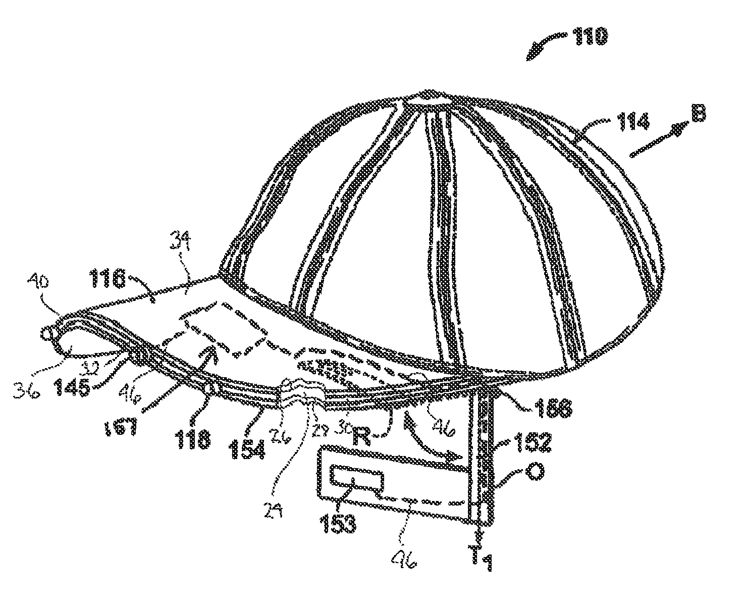
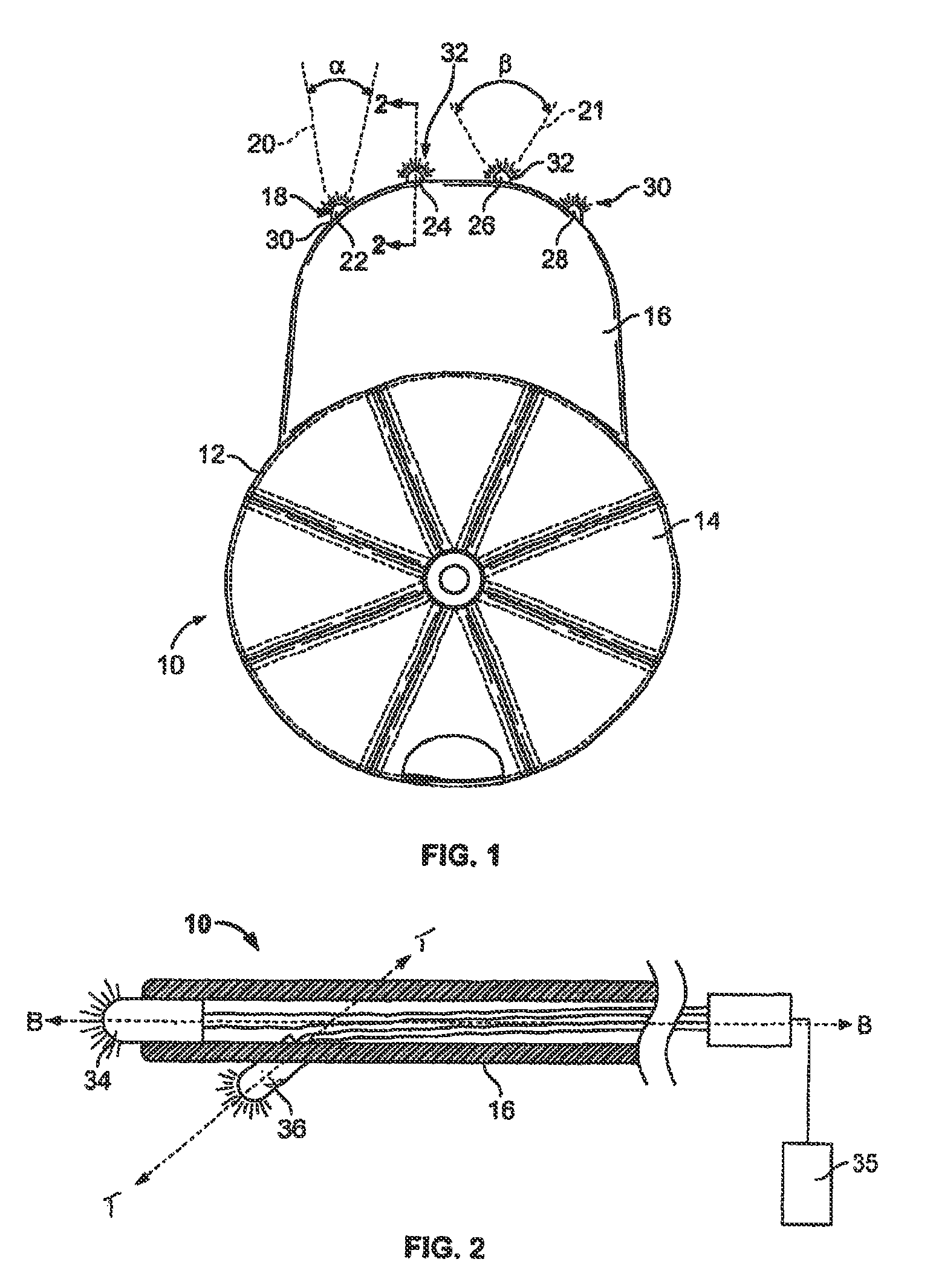
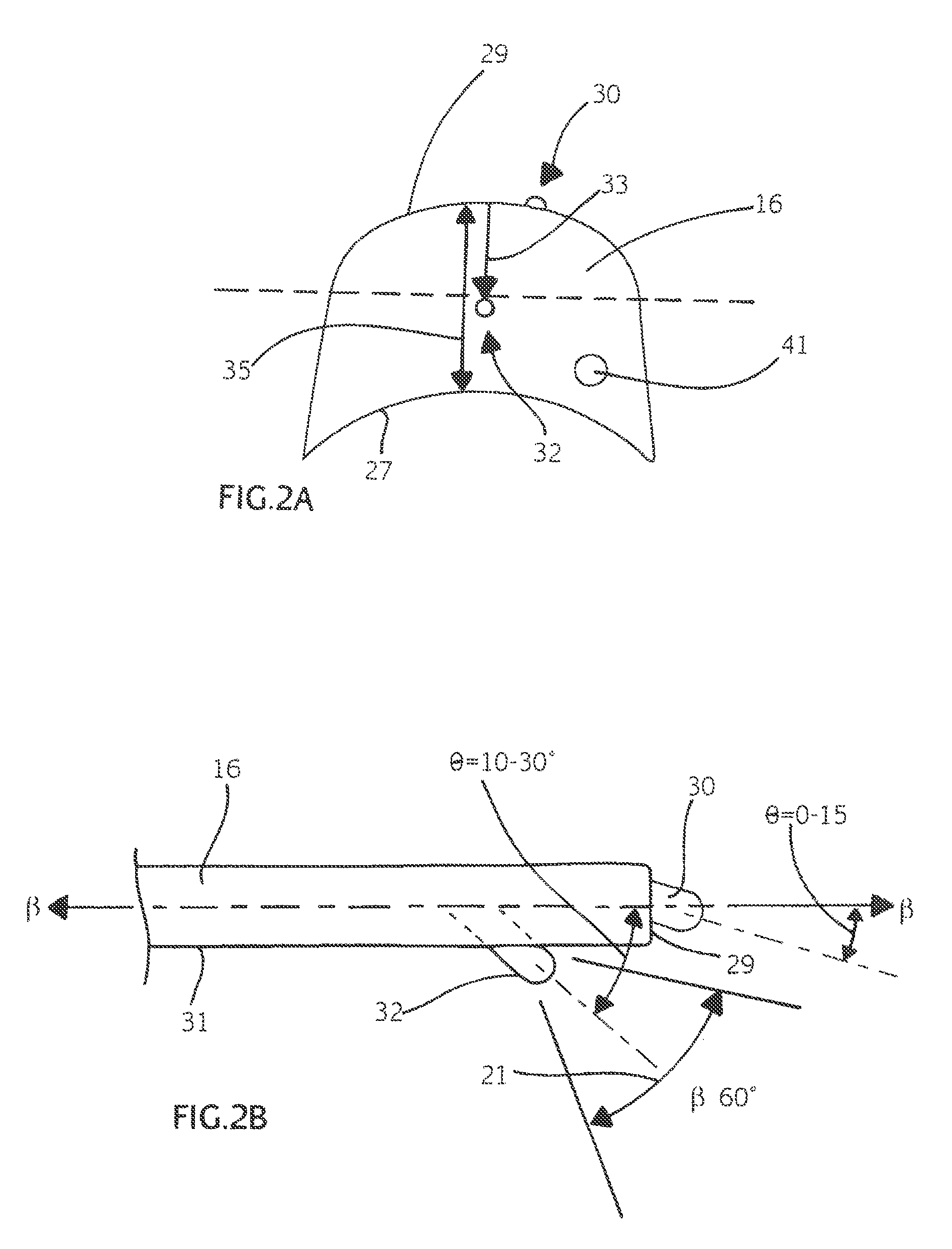
[0056]In general, the various aspects of the invention herein relate to hands-free lighting, components thereof, and other accessories therefor combined with the hands-free lighting. As further described below, the hands-free lighting may include lighted headgear such as hats, including baseball caps, hoods, and other lighted clothing items having the lights positioned thereon to provide lighting forwardly of the wearer. The hands-free lighting include configurations to provide illumination in multiple directions, streamlined configurations to dissipate heat generated by the light source, multi-functional switches concealed in the headgear, and robust power source holder configurations that generally reinforce connections to the battery yet still permit some flexibility of the power source holder. Other accessories associated with the lighted headgear include a camera mounted to headgear having a flash thereon configured to reduce the effects of red eye, removable packaging material...


PUM


Abstract

Headgear includes a brim portion and a power source. In one form, a camera is mounted to the brim portion such that the power source powers the camera. The camera includes a lens mounted to the brim portion and control circuitry for operating the camera mounted to the brim portion at least partially between upper and lower major surfaces thereof. In alternate forms, a heat sink can be mounted to the brim portion to dissipate heat generated by powered components of the headgear, such as the camera, a circuit board, a light source, or the like, and a rotary switch can be mounted to the brim portion for energizing the a light source and / or operating the camera.

Description

CROSS-REFERENCE TO RELATED APPLICATION[0001]This application is a continuation-in-part of International Application No. PCT / US2008 / 087542, filed Dec. 18, 2008, which claims the benefit of U.S. Provisional Application No. 61 / 014,726, filed Dec. 18, 2007, which are hereby incorporated by reference herein in their entirety. This application also claims the benefit of U.S. Provisional Application No. 61 / 330,185, filed Apr. 30, 2010, which is hereby incorporated by reference herein in its entirety.FIELD OF THE INVENTION[0002]The field relates to hands-free lighting devices and, in particular, to lighted hats, lighted clothing items, and other accessories and components associated with hands-free lighting devices.BACKGROUND OF THE INVENTION[0003]Often an individual desires a light focused to illuminate an area while performing a task or a light directed in a general outward direction for visibility. Holding a flashlight is an option, but such lighting devices are often cumbersome and may ...

Claims


Application Information

Patent Timeline
Patent Type & Authority Patents(United States)
IPC IPC(8): F21V21/084
CPCA42B1/245A42B1/244H04N5/2254H04N13/0207H04N13/207H04N23/531H04N23/55
Inventor WATERS
Owner WATERS
Why Eureka
Try Eureka