Angled emitter channel letter lighting

a technology of emitter and channel letter, which is applied in the direction of metal rolling stand, printed circuit non-printed electric component association, light support device, etc., can solve the problems of bulb failure, consuming a relatively large amount of power, and relatively short life (20,000 hours)

Active Publication Date: 2015-07-14
THE SLOAN COMPANY INC DBA SLOANLED
View PDF18 Cites 13 Cited by
  • Summary
  • Abstract
  • Description
  • Claims
  • Application Information

AI Technical Summary

Problems solved by technology

These light sources, however, have a relatively short life (20,000 hours), are fragile, operate at high voltage (7,000 to 15,000 volts for neon) and can consume a relatively large amount of power.
Neon bulbs can also experience difficulty with cold starting, which can lead to the bulb's failure.
These chains are typically sold at a cost per measure of length, and the cost per length is typically greater for lighting systems having higher density.
Conventional lighting units, however, offer little flexibility in reducing the number of LEDs in certain ones or all of the LED units in a chain.
Some lighting units incorporate the use of reflectors or a lens over these LEDs to help disperse the light, however these may cause a loss of light output due to the lens or reflector.

Method used


Image

  • Angled emitter channel letter lighting
  • Angled emitter channel letter lighting
  • Angled emitter channel letter lighting

Examples


Embodiment Construction

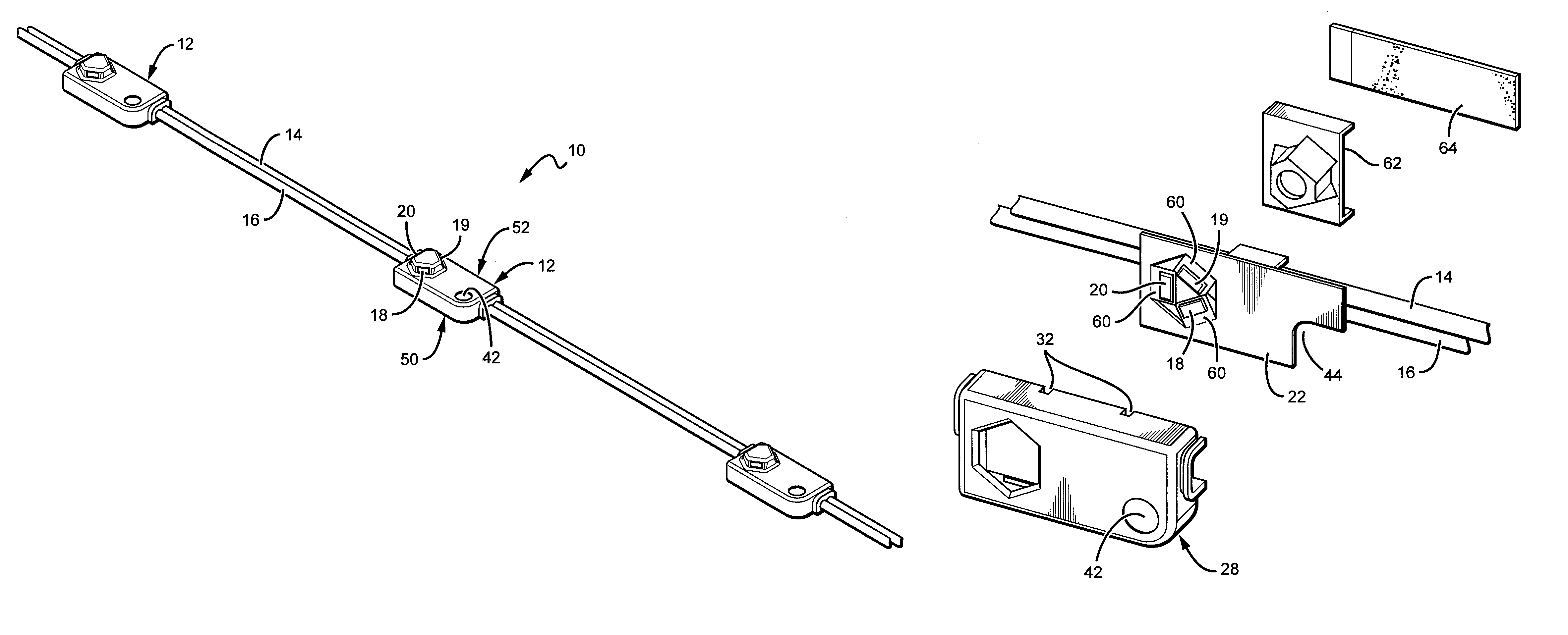
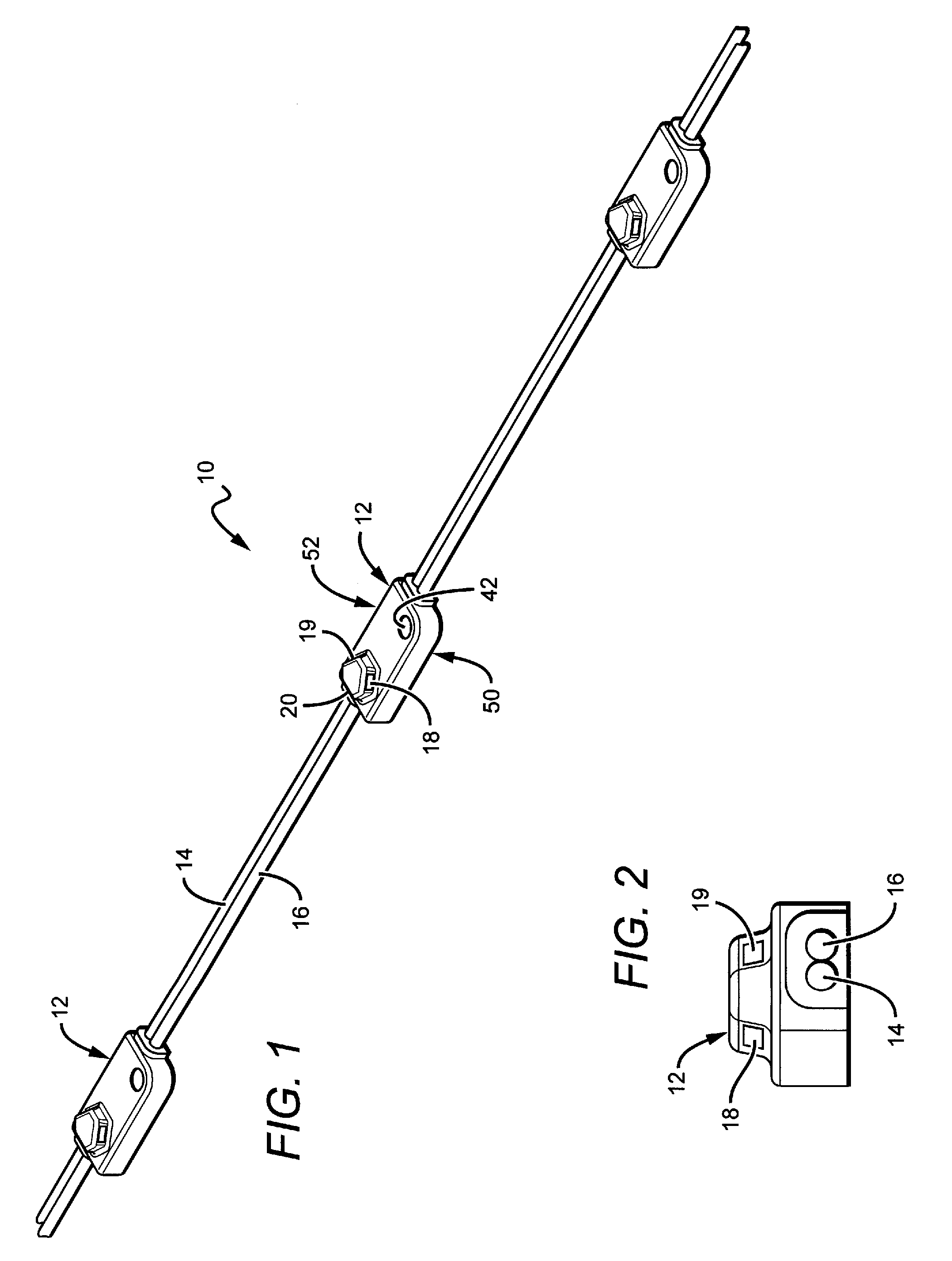
[0028]The present invention provides a lighting system that can be used in many different applications such as structural lighting, display lighting and ingress / egress lighting, but is particularly applicable to channel letter lighting. The systems according to the present invention provide lighting units that can be interconnected in a chain by electrical conductors so that an electrical signal applied to the input end of the conductors spreads to the lighting units, causing them to emit light. The lighting units can also be powered independently from other lighting units. According to the present invention, the LED units can be placed in a plastic housing. The side of the lighting unit which can be mounted on a surface will be referred to as the bottom 50 of the lighting unit (shown in FIG. 1). The surface opposite the bottom will be referred to as the top 52. The LEDs are placed in the housing in such a manner that they are on the top of the lighting unit, but angled away from th...


PUM

PropertyMeasurementUnit
voltageaaaaaaaaaa
depthsaaaaaaaaaa
depthaaaaaaaaaa

Abstract

The present embodiments provide channel letter lighting devices and / or systems. A lighting system, comprising a plurality of electrically connected lighting units, comprising conductors to provide an electrical signal to each of the units. Each of the lighting units comprise a housing, a printed circuit board (PCB) mounted within the housing and having a plurality of tabs and a plurality light emitting elements on the tabs. The tabs are angled in relation of the remainder of the PCB or housing. The electrical signal applied to the light emitting elements causes them to emit light substantially away from said housing. The lighting system further comprises a sealant within the housing filling cavities around the light emitting elements and the cavity around said PCB and a mounting mechanism for mounting the unit to a structure.

Description

[0001]This application is a continuation in part of Ser. No. 13 / 010,413 to Bruce Quaal et al., filed on Jan. 20, 2011, now abandoned also a continuation in part of Ser. No. 12 / 316,411 to Thomas C. Sloan, which was filed on Dec. 12, 2008, now abandoned and also claims the benefit of provisional application Ser. No. 61 / 297,681 to Drew Ferrie filed on Jan. 22, 2010 and provisional application Ser. No. 61 / 425,713 to Drew Ferrie, which was filed on Dec. 21, 2010. The contents of Ser. Nos. 12 / 316,411, 13 / 010,413, 61 / 425,713 and 61 / 297,681 are incorporated entirely herein by reference.BACKGROUND OF THE INVENTION[0002]1. Field of the Invention[0003]This invention relates to lighting units using angled lighting for illuminating channel letters and more particularly to LED based lighting units for illuminating channel letters with angled or side emitting LEDs.[0004]2. Description of the Related Art[0005]Recent developments in LEDs have resulted in devices that are brighter, more efficient and...

Claims


Application Information

Patent Timeline
Patent Type & Authority Patents(United States)
IPC IPC(8): F21V19/00H05K1/02G09F13/04G09F13/22F21V31/04F21V23/00F21V21/08F21V15/01F21S4/00H05K1/05H05K1/18F21V29/00F21Y101/02
CPCF21V19/003F21S4/003F21V15/01F21V19/001F21V21/0808F21V23/005F21V31/04G09F13/0404G09F13/22H05K1/0278F21V29/004F21Y2101/02G09F2013/222H05K1/05H05K1/189H05K2201/046H05K2201/09081H05K2201/10106Y10T29/49165Y10T29/49993F21S4/20F21Y2115/10F21Y2107/70F21V29/508F21V29/71F21S4/28
Inventor QUAAL, BRUCEFERRIE, DREWMEYER, AARON
Owner THE SLOAN COMPANY INC DBA SLOANLED
Why Eureka
Try Eureka