Lane keeping control system for vehicle

a technology of lane keeping control and vehicle, which is applied in the direction of automatic steering control, vehicle components, steering parts, etc., can solve the problems of poor controllability of target steering angle, poor stability of target steering angle control, and inability to satisfactorily respond to the driver's steering operation. achieve precise and stable control, improve vehicle behavior, and accelerate target course tracking performance

Active Publication Date: 2016-01-05
SUBARU CORP
View PDF13 Cites 2 Cited by
  • Summary
  • Abstract
  • Description
  • Claims
  • Application Information

AI Technical Summary

Benefits of technology

[0008]In view of the above problems, it is an object of the invention to provide a lane keeping system for a vehicle that can perform lane keeping control in which; precise and stable control can be performed when a driver entrusts a steering operation of a vehicle to the system; the control can continue without excessively interfering with a driver's steering intention when the driver applies a steering input to the system; and a balance between a rapid target course tracking performance and stable vehicle behavior can be kept preferably when the vehicle travels on the target course.

Problems solved by technology

Therefore, if the driver overrides the system using a vehicle steering device disclosed in JP-A No. 2007-125959, in which the vehicle steering device performs feedforward control and feedback control while changing the weighting therebetween on the basis of an amount of positional deviation between the target course and the vehicle traveling course, the lane keeping control system might not satisfactorily response to the driver's steering operation.
If the lane keeping control system controls against the driver's steering intention, there is a possibility that the driver may feel discomfort.
In such a case, tracking performance for the target course becomes good, but controllability of a target steering angle and vehicle behavior becomes worse in sensitivity and stability since the system mainly responds to a current lateral deviation alone.

Method used


Image

  • Lane keeping control system for vehicle
  • Lane keeping control system for vehicle
  • Lane keeping control system for vehicle

Examples


Embodiment Construction

[0017]Referring now to the drawings, an example of the invention will be described below.

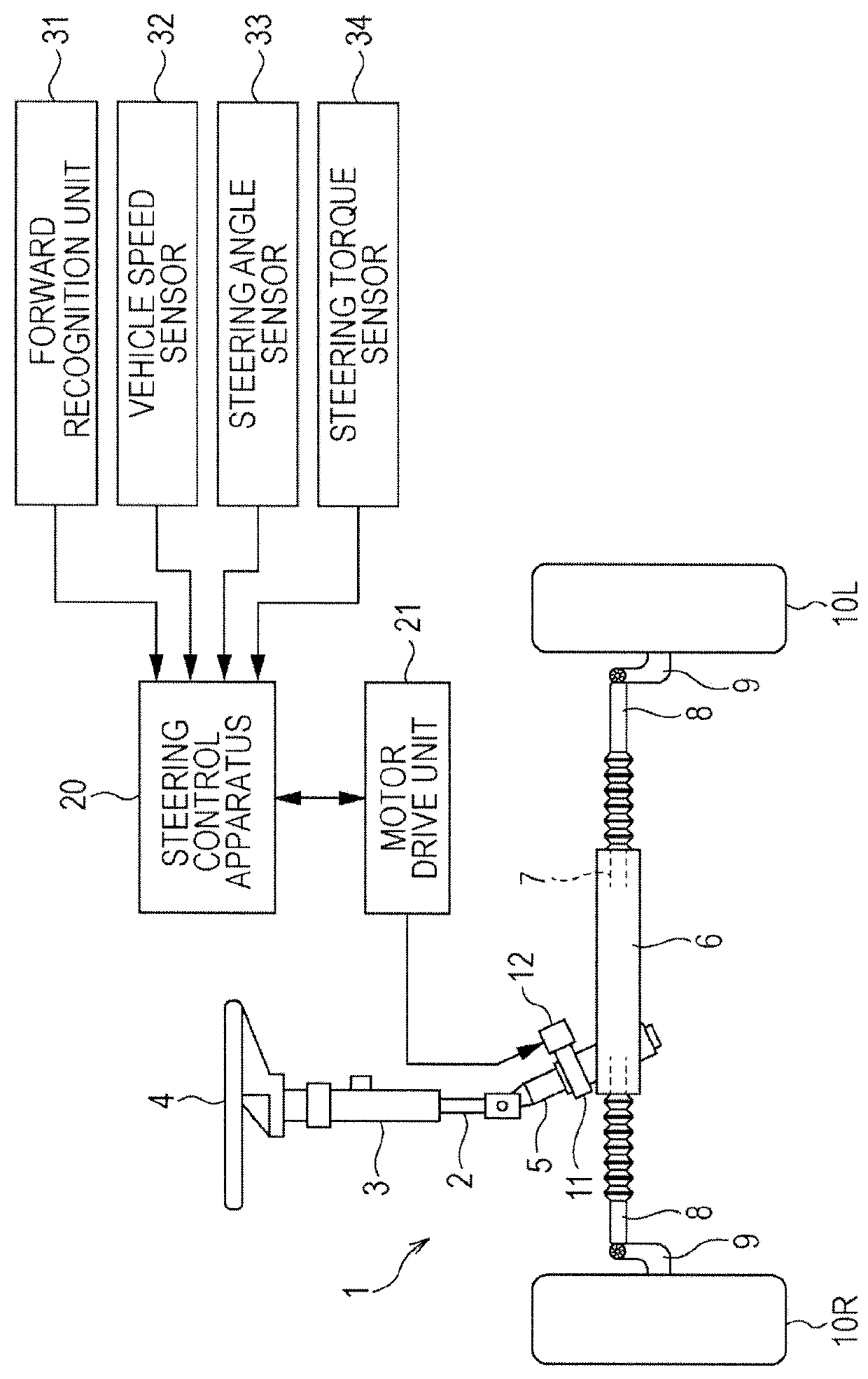
[0018]In FIG. 1, an electric power steering apparatus 1 can freely set a steering angle independently of a driver input. The electric power steering apparatus 1 includes a steering shaft 2 supported rotatably on a vehicle frame (not shown) through a steering column 3. An end of the steering shaft 2 extends toward a driver seat while the other end of the steering shaft 2 extends toward an engine compartment. A steering wheel 4 is secured to the end of the steering shaft 2 on the driver seat side while a pinion shaft 5 is connected to the other end of the steering shaft 2 on the engine compartment side.

[0019]A steering gear box 6 that extends in a vehicle width direction is located in the engine compartment. A rack shaft 7 is slidably inserted into the steering gear box 6. A pinion (not shown) formed on the pinion shaft 5 meshes with a rack (not shown) formed on the rack shaft 7. Thus, a rack and ...


PUM


Abstract

A vehicle lane keeping control system calculates a feedforward control amount on the basis of a vehicle traveling path, calculates a first positional deviation amount between a vehicle and a target course at a first forward attention point when the vehicle travels in a straight line to the first forward attention point if a steering torque exceeds a threshold value, calculates a first lateral position feedback control amount, calculates an amount of deviation between an estimated vehicle traveling path and the target course at a second forward attention point remote from the first forward attention point if the first lateral position feedback control amount is lower than the threshold value, calculates a second lateral position feedback control amount, and calculates an electric motor current value by using at least the feedforward control amount and one of the first and second lateral position feedback amounts.

Description

CROSS-REFERENCE TO RELATED APPLICATIONS[0001]The present application claims priority from Japanese Patent Application No. 2013-202059 filed on Sep. 27, 2013, the entire contents of which are hereby incorporated by reference.BACKGROUND[0002]1. Technical Field[0003]The present invention relates to a lane keeping control system that causes a vehicle to travel along a predetermined target course by driving an electric power steering motor.[0004]2. Related Art[0005]Recently, in order to reduce traffic accidents and driver's load, techniques concerning various lane keeping control systems that assist and control a steering operation to cause a vehicle to travel along a predetermined target course have been developed and proposed. For instance, Japanese Unexamined Patent Application Publication (JP-A) No. 2007-125959 discloses a steering system for a vehicle. Specifically, the steering system for the vehicle receives data on a target course and has a driver model that estimates a driver st...

Claims


Application Information

Patent Timeline
Patent Type & Authority Patents(United States)
IPC IPC(8): B60W30/10B62D1/00B62D6/00B62D15/02B60W30/12
CPCB60W30/12B62D15/025
Inventor OYAMA, HAJIME
Owner SUBARU CORP
Why Eureka
Try Eureka