Segmented directional backlight and related methods of backlight illumination

a backlight and segmented technology, applied in the field of displays, can solve the problems of limiting the viewing freedom of the display, increasing the level of image crosstalk, and non-uniform viewing windows, and achieve the effects of large back working distance, thin form factor, and high efficiency

Active Publication Date: 2016-02-02
REALD SPARK LLC
View PDF88 Cites 7 Cited by
  • Summary
  • Abstract
  • Description
  • Claims
  • Application Information

AI Technical Summary

Benefits of technology

[0007]Backlight units (BLUs) that employ folded optical systems such as stepped imaging directional backlights may be advantageously transparent to normally incident light. The transparency property enables valve array apparatuses such as stacked and tiled composite illumination systems of the present embodiments, where for example at least part of adjacent illuminators are hidden by or illuminate through each other. Such valve array illumination apparatus embodiments lead to increased brightness, local independent illumination and directional capabilities.
[0013]In embodiments, the optical function of the directional backlight can be provided by multiple stepped waveguides in which light passes from an external light source passes through a surface of the stepped waveguide in addition to the input aperture of the stepped waveguide. Advantageously such an arrangement provides additional optical functions to be provided in addition to the optical function provided by the respective stepped waveguide while preserving the advantages of high efficiency, large back working distance and thin form factor of the respective stepped waveguide.
[0014]Advantageously such an arrangement achieves a combination of optical functions including, but not limited to, increased brightness autostereoscopic display, a controllable landscape / portrait display, a 2D / 3D switchable display, increased display area, and high efficiency color display illumination. Further the optical properties of the output can be modified to increase uniformity and widen viewing angle. Further, multiple viewers can be tracked independently.
[0015]Embodiments herein may provide an autostereoscopic display with large area and thin structure. Further, as will be described, the optical valves of the present disclosure may achieve thin optical components with large back working distances. Such components can be used in directional backlights, to provide directional displays including autostereoscopic displays. Further, embodiments may provide a controlled illuminator for the purposes of an efficient autostereoscopic display.
[0018]Directional backlights offer control over the illumination emanating from substantially the entire output surface controlled typically through modulation of independent LED light sources arranged at the input aperture side of an optical waveguide. Controlling the emitted light directional distribution can achieve single person viewing for a security function, where the display can only be seen by a single viewer from a limited range of angles; high electrical efficiency, where illumination is only provided over a small angular directional distribution; alternating left and right eye viewing for time sequential stereoscopic and autostereoscopic display; and low cost.

Problems solved by technology

Gaps between the pixels, for example for electrodes, typically produce non-uniform viewing windows.
Undesirably such displays exhibit image flicker as an observer moves laterally with respect to the display and so limit the viewing freedom of the display.
Such flicker can be reduced by defocusing the optical elements; however such defocusing results in increased levels of image cross talk and increases visual strain for an observer.
However, LCD displays struggle to meet various update requirements due to the modest response times and continuous scrolling and line-by-line updating provided in scrolling stereoscopic displays.

Method used


Image

  • Segmented directional backlight and related methods of backlight illumination
  • Segmented directional backlight and related methods of backlight illumination
  • Segmented directional backlight and related methods of backlight illumination

Examples


Embodiment Construction

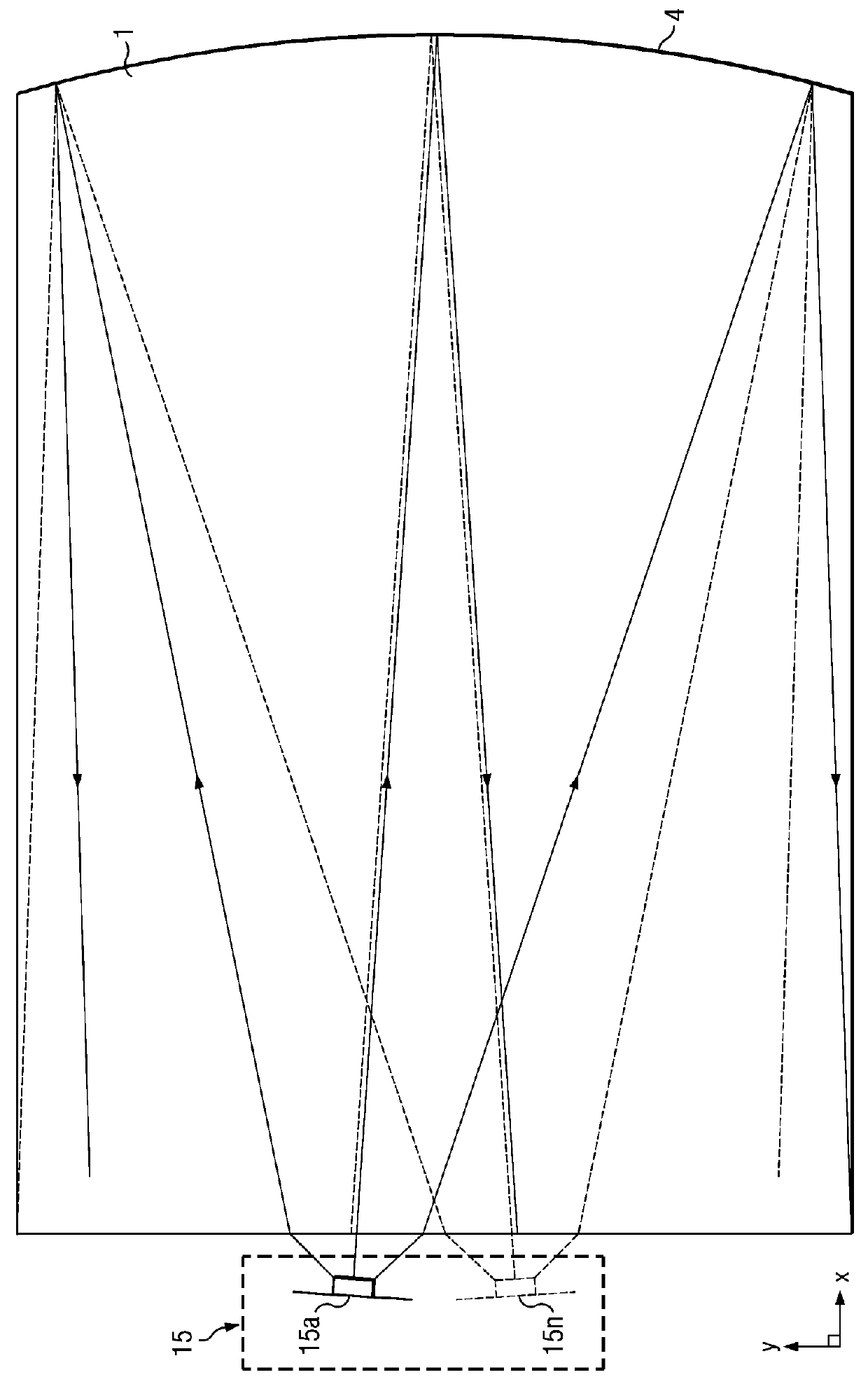
[0044]Time multiplexed autostereoscopic displays can advantageously improve the spatial resolution of autostereoscopic display by directing light from all of the pixels of a spatial light modulator to a first viewing window in a first time slot, and all of the pixels to a second viewing window in a second time slot. Thus an observer with eyes arranged to receive light in first and second viewing windows will see a full resolution image across the whole of the display over multiple time slots. Time multiplexed displays can advantageously achieve directional illumination by directing an illuminator array through a substantially transparent time multiplexed spatial light modulator using directional optical elements, wherein the directional optical elements substantially form an image of the illuminator array in the window plane.

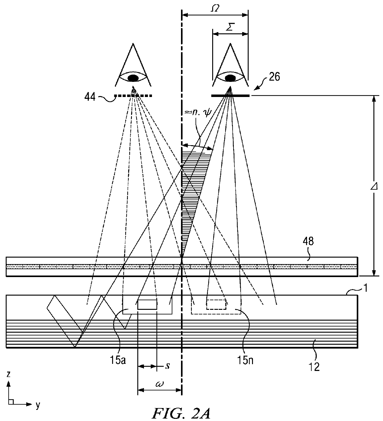
[0045]The uniformity of the viewing windows may be advantageously independent of the arrangement of pixels in the spatial light modulator. Advantageously, such ...


PUM


Abstract

Backlit display systems, such as those employed with LED backlit displays, including those configured for autostereoscopic operation, may employ synchronization between the backlight and the presentation of sequential left and right eye images at a frame rate exceeding approximately 100 Hz. To successfully directionally illuminate isolated frames, the disclosed principles provide for segmenting the directional illumination and introducing a phase shifted, synchronized, pulsed drive scheme for the illumination segments. Accordingly, the principles disclosed herein are directed to segmented directional illumination systems and related techniques for segmented directional backlight illumination.

Description

CROSS-REFERENCE TO RELATED APPLICATIONS[0001]This non-provisional application claims priority to U.S. App. Ser. No. 61 / 496,319, entitled “Segmented directional backlight,” filed Jun. 13, 2011. This application also claims priority to U.S. App. Ser. No. 61 / 649,124, entitled “Optical inline directional backlight apparatus and method thereof,” filed May 18, 2012. Further, this application is a continuation-in-part of U.S. application Ser. No. 13 / 300,293, entitled “Directional flat illuminators,” filed Nov. 18, 2011 which claims priority to U.S. App. Ser. No. 61 / 415,810, entitled “Directional flat illuminators,” filed Nov. 19, 2010. All of the aforementioned applications in this paragraph are herein incorporated by reference for all purposes.TECHNICAL FIELD[0002]The present disclosure generally relates to displays, and more specifically, to two dimensional and three dimensional display technologies and components.BACKGROUND[0003]Spatially multiplexed autostereoscopic displays typically ...

Claims


Application Information

Patent Timeline
Patent Type & Authority Patents(United States)
IPC IPC(8): G02B27/22F21V8/00G02B30/33
CPCG02B27/225G02B6/0048G02B30/33
Inventor ROBINSON, MICHAEL, G.
Owner REALD SPARK LLC
Why Eureka
Try Eureka