Reference voltage generating device and method

a reference voltage and generating device technology, applied in the field of electronic circuits, can solve the problems of delay in the booting speed of electronic products, the unstable state of the reference the likely long stabilization time of the reference voltage after power on, so as to shorten the stabilization time avoid prolonging the unstable state of the reference voltage, and save the effect of circuit board area

Active Publication Date: 2016-04-05
APPLE INC
View PDF3 Cites 1 Cited by
  • Summary
  • Abstract
  • Description
  • Claims
  • Application Information

AI Technical Summary

Benefits of technology

[0008]The invention is directed to a reference voltage generating device, which is capable of effectively shortening a stabilization time of a reference voltage, so as to avoid prolonging an unstable state of the reference voltage due to selection of a resistance of a filter, and achieving an effect of saving a circuit board area.
[0014]According to the above descriptions, in the reference voltage generating device of the invention, after the power on reset signal sends a power reset pulse, the charge supplying source connected to the power voltage is used to quickly charge the output voltage stored in the charge storage unit to a potential the same or similar with that of the reference voltage, and the reference voltage source is used to maintain the potential of the reference voltage. In this way, the reference voltage generating device can effectively shorten the stabilization time of the reference voltage, so as to avoid prolonging the unstable state of the reference voltage due to selection of a capacitance value, the low-pass filter, etc.

Problems solved by technology

Namely, a stabilization time of the reference voltage after power on is probably too long, which delays a booting speed of the electronic product.

Method used


Image

  • Reference voltage generating device and method
  • Reference voltage generating device and method
  • Reference voltage generating device and method

Examples


Embodiment Construction

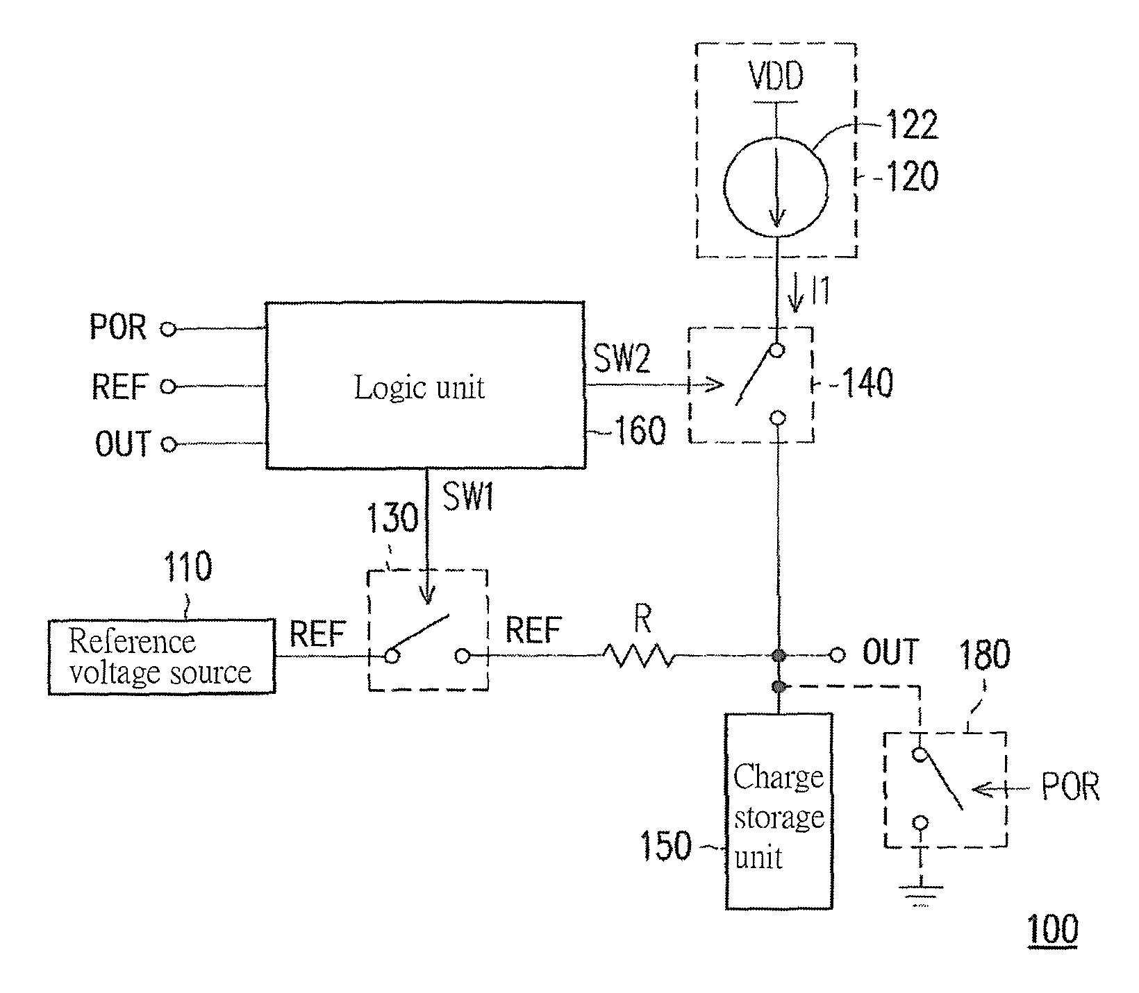
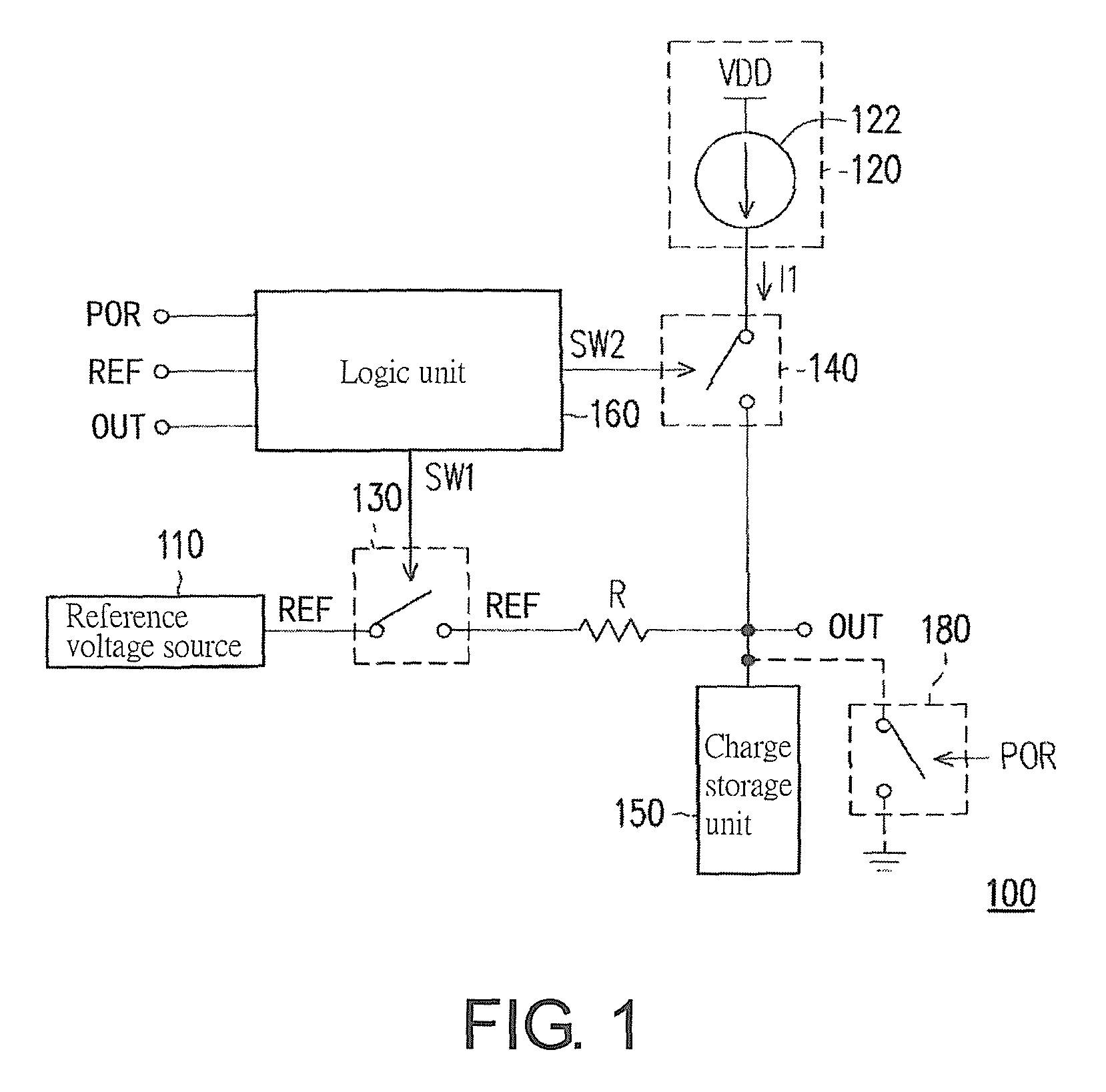
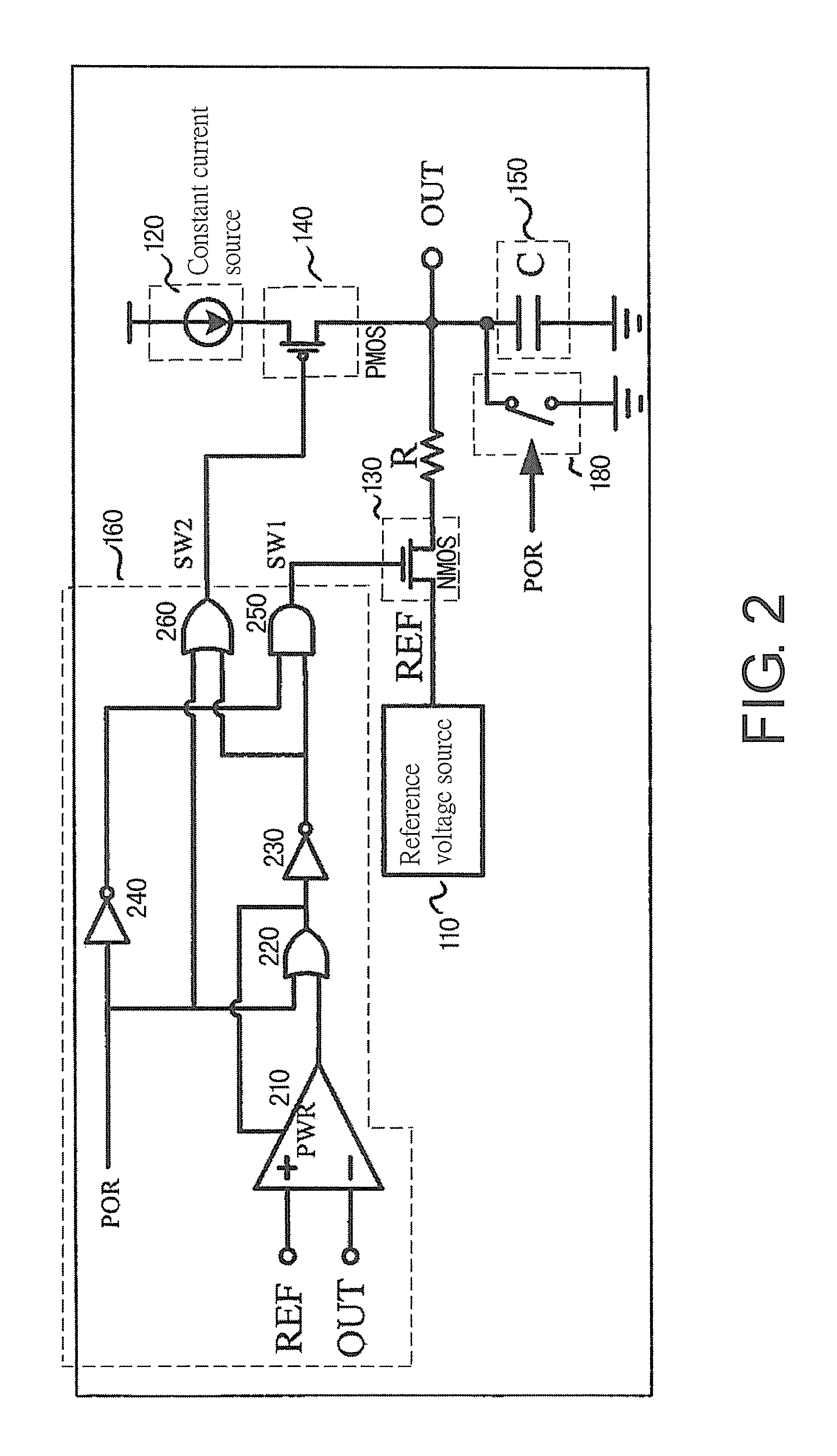
[0022]In order to avoid a situation that a post low-pass filter and / or a capacitor component therein delays a stabilization time of a reference voltage generated by a reference voltage source, in a reference voltage generating device provided by the invention, a charge supply source connected to a power voltage is used to adjust an output voltage, such that the output voltage can be quickly charged to potential the same or similar with that of the reference voltage. Moreover, when the potential of the output voltage is greater than or equal to the potential of the reference voltage, the reference voltage source is used to maintain the output voltage to the potential of the reference voltage. In this way, the reference voltage generating device of the invention can effectively shorten the stabilization time of the reference voltage, and meanwhile maintain an effect of a low-pass filter, so as to avoid prolonging the unstable state of the reference voltage due to selection of a capaci...


PUM


Abstract

A reference voltage generating device including a reference voltage source, a charge supplying source, a first switch, a second switch, a charge storage unit and a logic unit is provided. First terminals of the first and second switches are respectively coupled to the output terminal of the reference voltage source and the charge supplying source. When a power on reset signal is received, the first switch is turned off and the second switch is turned on, such that the charge supplying source quickly charges the charge storage unit. When the output voltage is greater than or equal to the reference voltage, the first switch is turned on and the second switch is turned off, such that the reference voltage source maintains the output voltage to the reference voltage.

Description

CROSS-REFERENCE TO RELATED APPLICATION[0001]This application claims the priority benefit of China application serial no. 201410068218.0, filed on Feb. 27, 2014. The entirety of the above-mentioned patent application is hereby incorporated by reference herein and made a part of this specification.BACKGROUND[0002]1. Technical Field[0003]The invention relates to an electronic circuit, and particularly relates to a reference voltage generating device and method thereof.[0004]2. Related Art[0005]Portable electronic products are all developed towards a design trend of low power consumption, fast booting speed, etc., so as to increase a usage and standby time of the electronic products under a same power capacity, and improve consumer's purchase willingness and user experience. Generally, an electronic circuit requires a reference voltage source non-related with an input power and an ambient temperature in internal thereof, such that a processing chip in the electronic circuit can determin...

Claims


Application Information

Patent Timeline
Patent Type & Authority Patents(United States)
IPC IPC(8): H03L7/00G05F1/67
CPCG05F1/67H03K19/0016G05F1/468
Inventor CHEN, PING-HSINGYU, MING-YI
Owner APPLE INC
Why Eureka
Try Eureka