Steering device

a steering device and steering column technology, applied in the direction of steering columns, steering parts, vehicle components, etc., can solve the problems of difficult to reduce the setting value of the separation load, difficult to perform the steering operation later, etc., to achieve suppress the separation, facilitate the elastic deformation, and prevent the separation of the hook portion

Active Publication Date: 2016-08-23
NSK LTD
View PDF15 Cites 8 Cited by
  • Summary
  • Abstract
  • Description
  • Claims
  • Application Information

AI Technical Summary

Benefits of technology

[0011]Accordingly, in a steering device according to the invention, when an excessive load is applied to a steering wheel, the load is transmitted to an inner column through an input shaft, and hence the inner column is moved forward. When the inner column moves, a base plate which is fixed through a fixing tool moves forward together. Meanwhile, an inner column bracket which is supported by a telescopic friction plate does not move. For this reason, since a shear force is applied to a connection member, the connection member is cut when the load exceeds the allowable shear force of the connection member. When the connection member is cut, the connection between the inner column and the inner column bracket is released. When the connection between the inner column and the inner column bracket is released, the inner column is supported in the axial direction by a friction force generated between the inner column and an outer column. For this reason, the inner column of the steering column may move toward the front side of the vehicle. Further, even when the connection member is cut, the outer column is supported by the outer column bracket fixed to a vehicle body side member. Further, the inner column is supported by the outer column. For this reason, even when the connection member is cut, the steering column is not dropped. Thus, the steering device according to the invention may suppress a problem in which the steering column is dropped by an erroneous operation even when the setting value of the separation load in which the steering column moves toward the front side of the vehicle is decreased.
[0021]According to the invention, even when a setting value of a separation load, in which the steering column moves toward the front side of a vehicle body, is decreased, it is possible to provide a steering device capable of suppressing a problem where a steering column is dropped by an erroneous operation.

Problems solved by technology

When the steering column is dropped due to the erroneous operation, it is difficult to perform the steering operation later.
For this reason, it is difficult to decrease the setting value for the separation load.

Method used


Image

  • Steering device
  • Steering device
  • Steering device

Examples


fourth embodiments

First to Fourth Embodiments

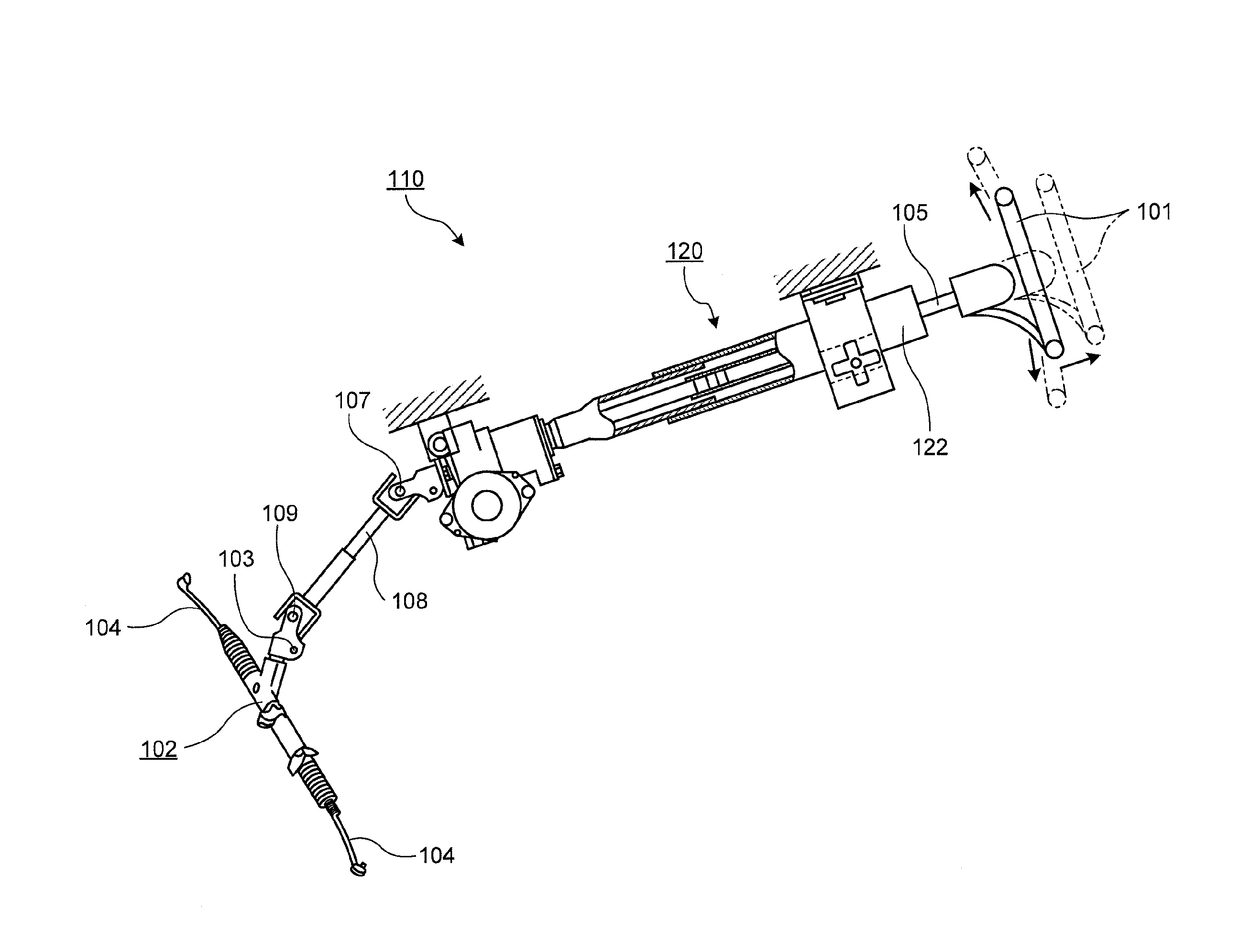
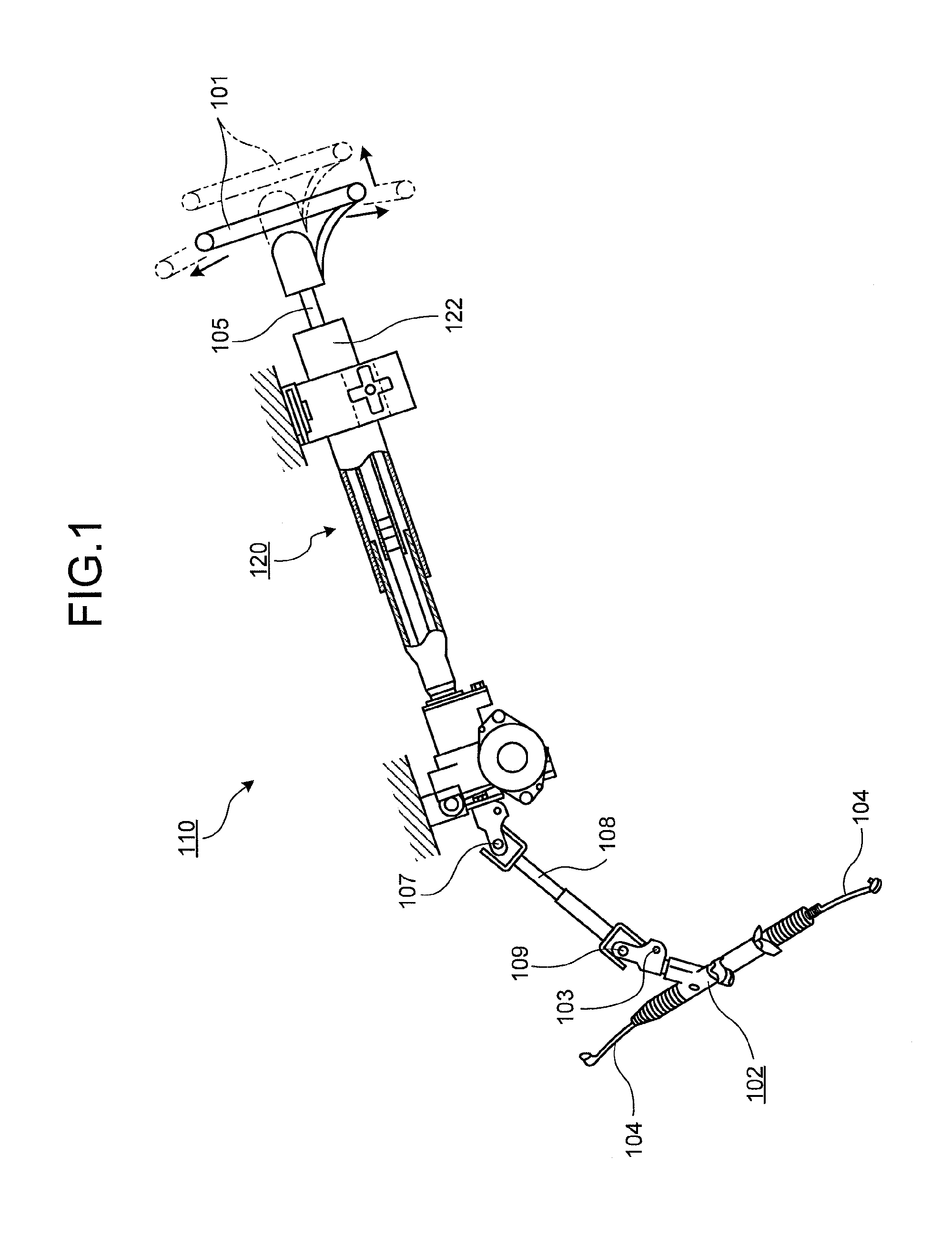
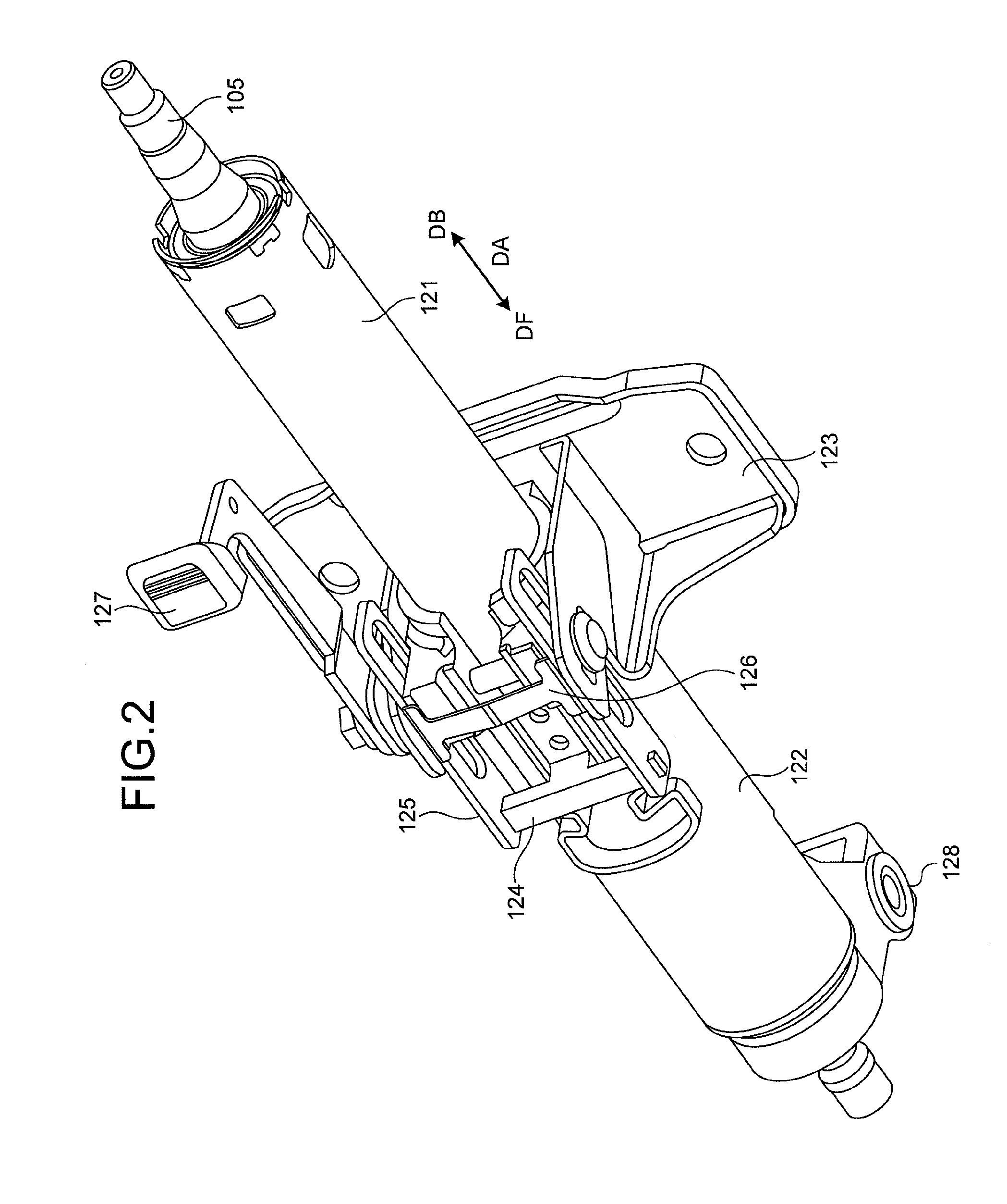
[0064]Hereinafter, this structure will be described in detail with reference to FIGS. 1 to 23D. FIGS. 1 to 4 schematically illustrate the first to fourth embodiments. FIGS. 5 to 10 specifically illustrate the structure of the first embodiment. Similarly, FIGS. 11 to 15 specifically illustrate the structure of the second embodiment, and FIGS. 16 to 23D specifically illustrate the structure of the third embodiment. In FIG. 2, the axial direction DA indicates the axial direction of the steering shaft, and the front side DF and the rear side DB indicate the front side and the rear side of the vehicle body when the steering device is attached to the vehicle body.

[0065]The first embodiment relates to a steering column apparatus 120 that supports a steering shaft including a male steering shaft 106 and a female steering shaft 105. Here, a steering column includes an inner column 121 and an outer column 122 and is contracted in the axial direction so as to be adju...

fifth embodiment

Modified Example of Fifth Embodiment

[0115]FIG. 34 is a cross-sectional view illustrating a steering device according to a modified example of the fifth embodiment when taken along the line corresponding to the line e-e of FIG. 26. FIG. 35 is an enlarged diagram illustrating the periphery of the connection member of FIG. 34. FIG. 36 is a diagram illustrating a state after the connection member according to the modified example of the fifth embodiment is sheared. The steering device 100 according to the modified example of the fifth embodiment is different from that of the fifth embodiment in that a connection member P is a resinous pin. In addition, the same reference signs will be given to the same components as those of the above-described embodiments, and the repetitive description thereof will not be presented.

[0116]As illustrated in FIGS. 34 and 35, when the connection member P is inserted into a position straddling the first hole 6h and the second hole 43h, the leg portion 43 o...

sixth embodiment

[0129]FIG. 37 is a cross-sectional view illustrating a steering device according to a sixth embodiment when taken along the line corresponding to the line e-e of FIG. 26. FIG. 38 is an enlarged diagram illustrating a bottom surface of the steering device according to the sixth embodiment. FIGS. 39A and 39B are perspective views illustrating an inner column bracket according to the sixth embodiment when viewed from the upside and the downside. FIG. 40 is a perspective view illustrating a base plate according to the sixth embodiment. The steering device 100 is different from that of the fifth embodiment in that the connection member P is a ball plunger B. In addition, the same reference signs will be given to the same components as those of the above-described embodiments, and the repetitive description thereof will not be presented.

[0130]As illustrated in FIG. 37, since the ball plunger B is inserted into a position straddling the first hole 6h and the main body screw hole portion B1...


PUM


Abstract

A steering device which contracts by an impulse load. A steering device includes an inner column having a cylindrical shape, a base plate having a first hole opened therein, an outer column having a cylindrical shape into which at least a part of the inner column is inserted, and having a slit formed by notching one insertion side end of the inner column, an outer column bracket to tighten the outer column along with a telescopic friction plate, and a connection member provided at a position straddling the first hole and a second hole, and detachably connecting the base plate and the inner column bracket.

Description

CROSS REFERENCE TO RELATED APPLICATIONS[0001]This is a National Stage of International Application No. PCT / JP2014 / 077725 filed Oct. 17, 2014, claiming priority based on Japanese Patent Application No. 2013-225851 filed Oct. 30, 2013, Japanese Patent Application No. 2013-260159 filed Dec. 17, 2013, Japanese Patent Application No. 2014-031692 filed Feb. 21, 2014, and Japanese Patent Application No. 2014-162386 filed Aug. 8, 2014, the contents of all of which are incorporated herein by reference in their entirety.BACKGROUND OF THE INVENTION[0002]1. Field of the Invention[0003]The present invention relates to a steering device.[0004]2. Description of the Related Art[0005]As a structure for supporting a steering device that gives a rudder angle to a vehicle wheel with the rotation of a steering wheel, a technique using a capsule is widely known. For example, in a technique disclosed in Prior Art 1, when an excessive load is applied to a steering column attached to a vehicle body through ...

Claims


Application Information

Patent Timeline
Patent Type & Authority Patents(United States)
IPC IPC(8): B62D1/19B62D1/184B62D1/185
CPCB62D1/184B62D1/195B62D1/185B62D1/192
Inventor JOHTA, MASAYAKOJIMA, HIDEKIHAGIWARA, WATARUORIHARA, DAIKISUZUKI, RYOICHI
Owner NSK LTD
Why Eureka
Try Eureka