
Flat clinch stapler anvil assembly

a stapler and flat clinch technology, applied in the field of flat clinch stapler anvil assembly, can solve the problems of limited paper stack maximum thickness, complicated linkage, and omission of the option of opening the base, and achieve the effect of effective flat clinch operation, high speed, and useful motion and

Active Publication Date: 2017-03-14
WORKTOOLS
View PDF70 Cites 5 Cited by
  • Summary
  • Abstract
  • Description
  • Claims
  • Application Information

AI Technical Summary

Benefits of technology

The patent relates to a flat clinch anvil used in stapling processes. The technical effects of the invention include high-speed operation of the staple ejection and efficient operation of the deflecting arms. The structure of the anvil is designed to have minimal inertia and low weight, allowing for useful motion upon the staple. There is no need for external linkages beyond the ejecting staple to actuate the system. The weight of the reciprocating arm is comparable to that of a staple. The technical effects are achieved through the use of a spring-energized stapler or a solenoid powered electric stapler.

Problems solved by technology

Further, the maximum thickness of a paper stack is limited since a very short leg segment cannot be looped.
Further, this linkage is mechanically complex.
Such connection also normally precludes an option to open the base away from the body for use as a tacker since the body and base are tied together by this flat clinch linkage.

Method used


Image

  • Flat clinch stapler anvil assembly
  • Flat clinch stapler anvil assembly
  • Flat clinch stapler anvil assembly

Examples


Embodiment Construction

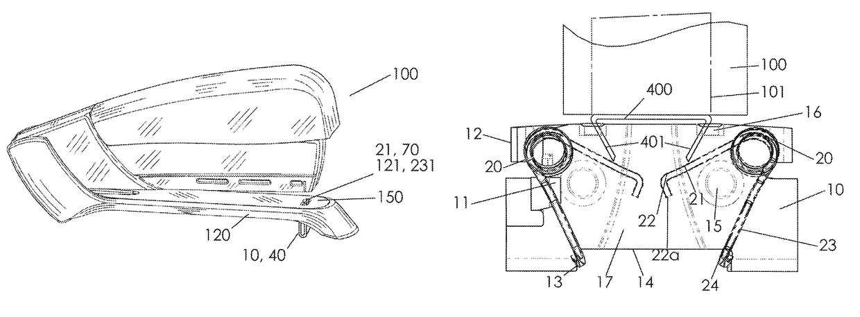
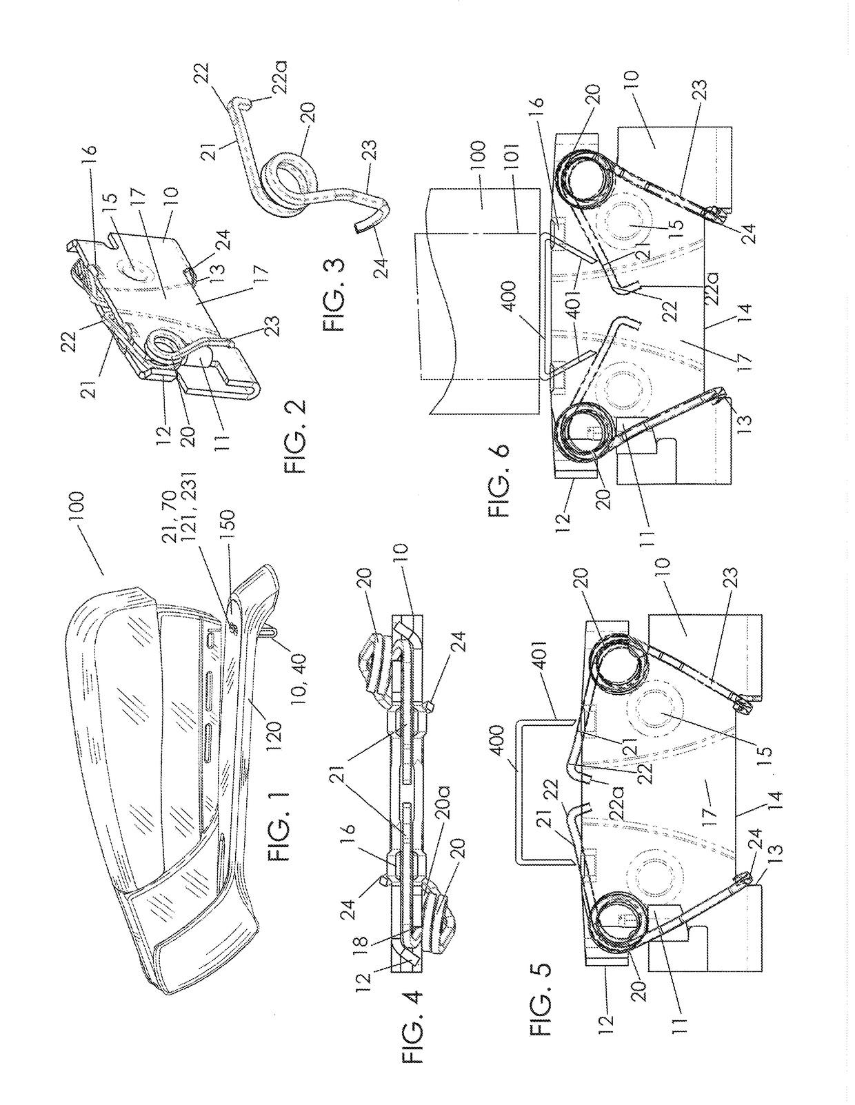
[0049]FIG. 1 shows an exemplary desktop stapler 100 including a stapler body supporting operative components with exemplary frame 10, 40 of a flat clinch anvil assembly fitted to stapler base 120. Other anvil frames and assemblies as illustrated or anticipated by the invention may be fitted to base 120 although the assemblies of FIGS. 2 to 16 is used in for simplicity in the present context of stapler 100. The stapler body is able to eject staple fasteners toward the base during an operating cycle of the stapler. During such operating cycle (not shown), a staple fed from a rack advanced on a guide track is suddenly ejected from the stapler body by impact blow. The stapler operative cycle may be of a type, for example, disclosed in U.S. Pat. No. 6,918,525 (Marks), titled “Spring Energized Desktop Stapler,” which contents are incorporated by reference. A space between the stapler underside and the base is able to receive papers or stacked sheet media to be stapled. The stapler pivots ...


PUM


Abstract

A flat clinch assembly fits upon or within a base of a stapling device. The assembly preferably includes a slot with extended resiliently biased arms or toggles, where a rest position has the arms at or near a level of a working surface. An ejecting staple deflects and energizes the arms to cause the arms to rotate and create a clearance recess whereby points of the staple legs slide inward along the anvil. A restorative bias acting on the arms causes the arms to rebound to a rest position and to bend the legs upward. The legs thereby are normally pressed flat against the back sheet of a paper stack at the working surface. The arms or toggles are lightweight whereby the inertia of a fast moving staple moves the arms or toggles.

Description

CROSS-REFERENCE TO RELATED APPLICATIONS[0001]This non-provisional patent application claims benefit of priority from U.S. provisional patent application No. 61 / 755,894, filed on Jan. 23, 2013, the contents of which are incorporated by reference.FIELD OF THE INVENTION[0002]The present invention relates to improvements to stapling. More precisely, the present invention relates to a mechanism for flat clinched staple legs.BACKGROUND[0003]In desktop or other office and related type staplers, an anvil operates below a stack of papers to bend staple legs behind the paper. Such clinching binds the papers together. A typical anvil is made of a hard steel plate including two adjacent arcuate depressions. During the stapling process, the staple legs enter an outer portion of the depressions and slide within the depressions to form a rounded or looped clinch. The legs are formed at the same time that the staple is being ejected from the stapler. This system is simple and normally effective for...

Claims


Application Information

Patent Timeline
Patent Type & Authority Patents(United States)
IPC IPC(8): B25C5/02B27F7/19B25C5/15
CPCB25C5/0207B25C5/02B27F7/19B25C5/0264B25C5/15
Inventor MARKS, JOEL S.
Owner WORKTOOLS
Learn More