Hook with magnetic closure

a technology of magnetic closure and hook, which is applied in the direction of hooks, applications, fastening means, etc., can solve the problems of difficult to purposely open the hook to attach or secure something, the protruding knob used to pull and hold open the spring is often uncomfortable or even painful to operate, and the inability to secure an item on the arm. , to achieve the effect of reducing or preventing accidental openings

Active Publication Date: 2017-10-03
MITCHELL LUCY A
View PDF30 Cites 5 Cited by
  • Summary
  • Abstract
  • Description
  • Claims
  • Application Information

AI Technical Summary

Benefits of technology

[0015]A third object of the invention is to provide a hook that is safe to use and easy to open.
[0017]An additional object of the invention is to provide a hook in which the closing force is becomes stronger as the closure approaches the closed position.
[0019]A still further object of the invention is to offer a hook devised to decrease or prevent accidental openings while simultaneously configured to open easily.
[0020]An additional object of the invention is to supply a hook configured to include features that provide stability while the hook is held in the open position.

Problems solved by technology

Thus, in prior art hooks of this type, it is harder to purposely open the hook to attach or secure something than it is to accidentally lose something off the hook.
The prior art design tends to cause injuries in that the compressed spring can snap forward unexpectedly injuring the user.
In addition, the protruding knob used to pull and hold open the spring is often uncomfortable or even painful to operate.
The clamp has the disadvantage of not securing an item on the arm and not enabling secure movement of the secured item when the disclosed clamp is closed.
However, the clip requires that a magnet be in the instrument that is held by the clip thereby introducing a limitation to its usefulness in that nonmagnetic devices cannot be securely held by the clip.
In addition, the use of a trigger mechanism increases the possibility of injury caused by the inadvertent activation of the biasing trigger.
In addition, as mentioned above, the clasps and hooks currently in the field are easily opened accidentally because of the lack of positive force holding the closure in the closed position.

Method used


Image

  • Hook with magnetic closure
  • Hook with magnetic closure
  • Hook with magnetic closure

Examples


Embodiment Construction

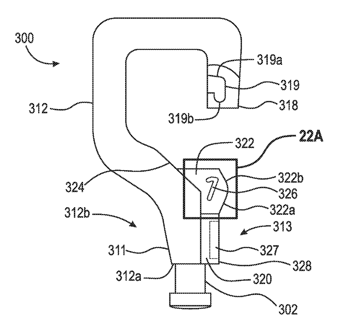
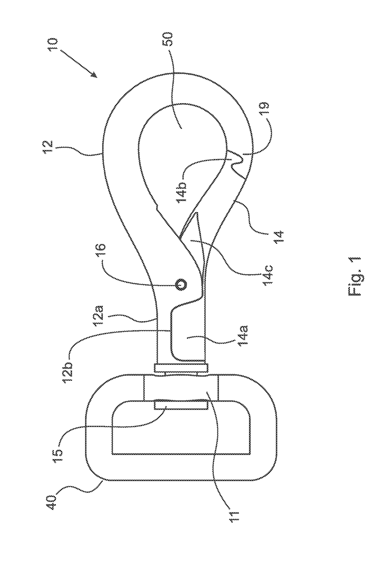
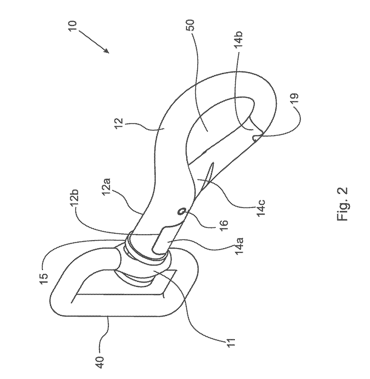
[0060]At the outset, it should be appreciated that like drawing numbers on different drawing views identify identical structural elements of the invention. It also should be appreciated that figure proportions and angles are not always to scale in order to clearly portray the attributes of the present invention.

[0061]While the present invention is described with respect to what is presently considered to be the preferred embodiments, it is understood that the invention is not limited to the disclosed embodiments. The present invention is intended to cover various modifications and equivalent arrangements included within the spirit and scope of the appended claims.

[0062]Furthermore, it is understood that this invention is not limited to the particular methodology, materials and modifications described and as such may, of course, vary. It is also understood that the terminology used herein is for the purpose of describing particular aspects only, and is not intended to limit the scope...


PUM

PropertyMeasurementUnit
distanceaaaaaaaaaa
sizeaaaaaaaaaa
sizeaaaaaaaaaa

Abstract

A hook formed into a body formed into a hook shape and having a neck and fabricated from nonferromagnetic material with the body having a first end and a second end. The neck is proximate the first end. One side of the neck includes a center ridge with a flat top surface with either a magnet or ferromagnetic material embedded in the center ridge. The hook also includes a closure having a first closure end and a second closure end and a channel with a floor flanked by two lateral sides. A second magnet or a ferromagnetic material is embedded into the floor opposed to the first magnet or ferromagnetic material. The closure being pivotally and / or pivotally and slidably attached to the hook body by at least one pin. The magnet(s) and / or ferromagnetic material hold the closure in a closed position enclosing a defined space.

Description

CROSS REFERENCE TO RELATED APPLICATIONS[0001]This application is filed under 35 U.S.C. §120 as a continuation-in-part of U.S. patent application Ser. No. 13 / 947,588, now U.S. Pat. No. 9,032,594, filed Jul. 22, 2013, which application claims priority under 35 U.S.C. §120 as a continuation-in-part to U.S. patent application Ser. No. 13 / 596,616, now U.S. Pat. No. 9,080,595, filed Aug. 28, 2012, which application claims priority under 35 U.S.C. §120 as a continuation-in-part of U.S. patent application Ser. No. 12 / 881,744, now U.S. Pat. No. 8,448,307, filed Sep. 14, 2010, which applications are incorporated herein by reference in their entireties.FIELD OF THE INVENTION[0002]The present invention relates generally to the field of hooks and clasps, specifically to hooks and clasps with a closing mechanism, and more specifically to closures that are manually operated.BACKGROUND OF THE INVENTION[0003]Manually operated hooks or clasps are found in the prior art that operate using a spring tha...

Claims


Application Information

Patent Timeline
Patent Type & Authority Patents(United States)
IPC IPC(8): F16B45/02A44C5/20F16B1/00F16B45/04H01F7/02
CPCF16B45/02A44C5/2038F16B1/00F16B45/04H01F7/0263A44D2203/00F16B2001/0035Y10T24/32Y10T24/4533Y10T24/45435F16B2200/83F16B45/024F16B45/023
Inventor MITCHELL, LUCY A.
Owner MITCHELL LUCY A
Why Eureka
Try Eureka