
Control method and apparatus for series resonance DC/DC converter
A technology of DC converter and series resonance, which is applied in the field of control method and device of series resonant DC/DC converter, can solve the problems such as frequency modulation control magnetic components are difficult to optimize circuit loss, etc., and achieve good reliability and dynamic characteristics, and circuit Simple, strong engineering effect
Patent Information
- Authority / Receiving Office
- CN · China
- Patent Type
- Patents(China)
- Current Assignee / Owner
- Publication Date
- 2009-09-16
- Estimated Expiration
- Not applicable · inactive patent
Smart Images
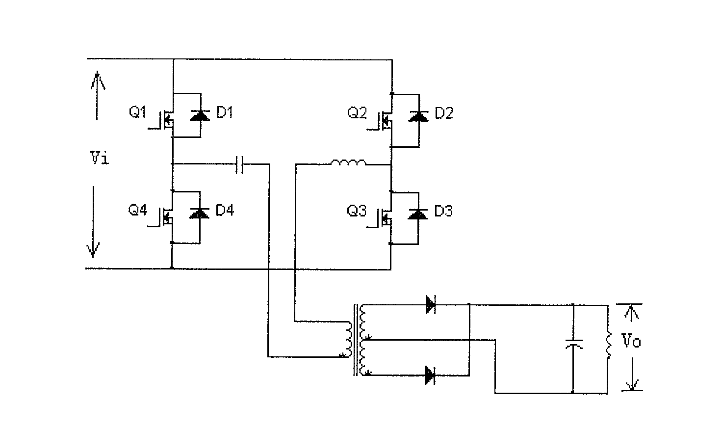
Figure 1 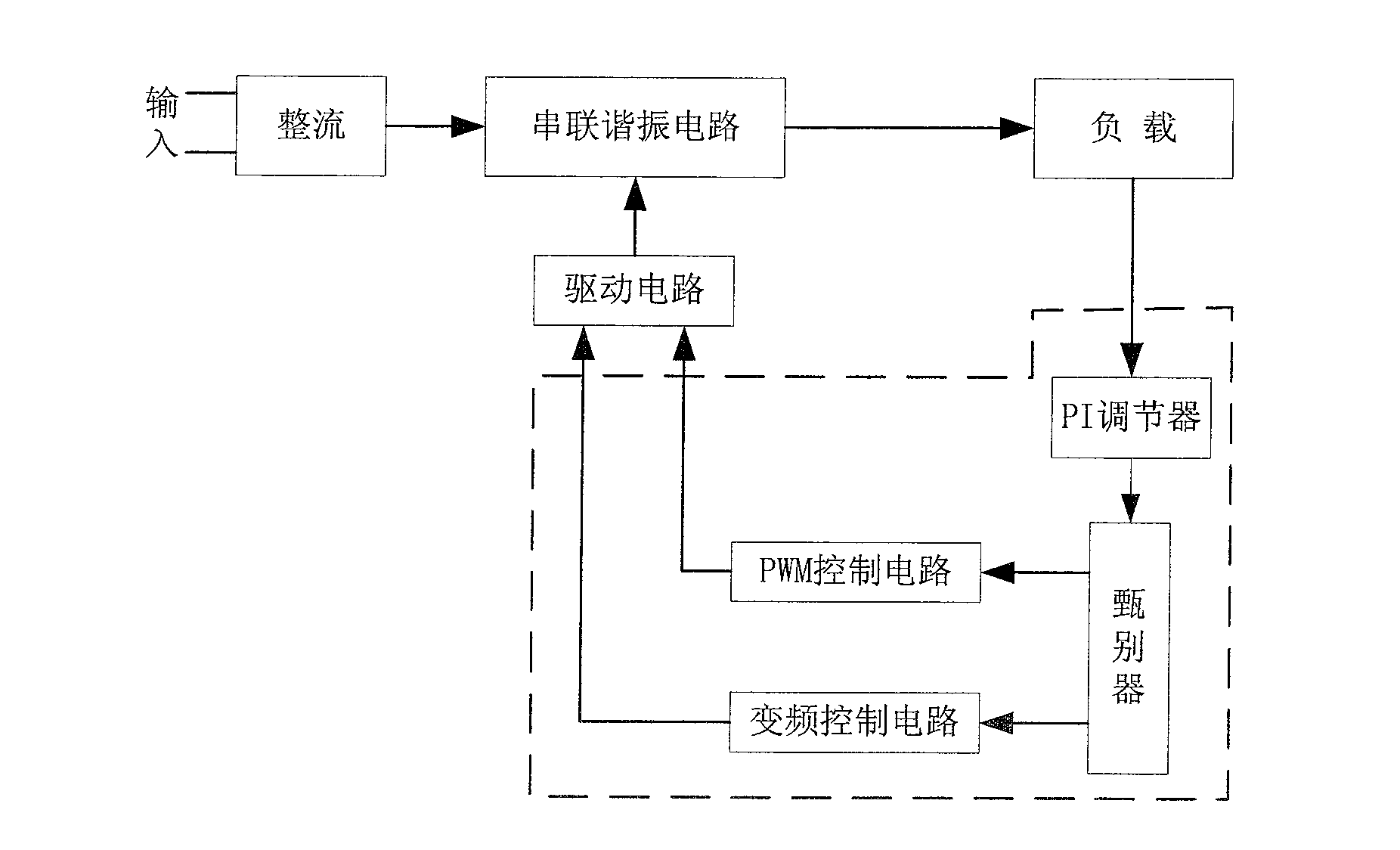
Figure 2 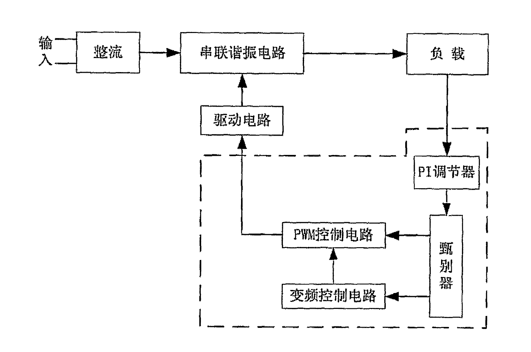
Figure 3
Abstract
Description
technical field
[0001] The invention relates to DC power conversion technology, in particular to a control method and device for a series resonant DC / DC (DC / DC) converter. Background technique
[0002] Miniaturization and high frequency are the development trend of power supply today, but the switching frequency is too high to bring about the problem of excessive loss of the switching tube, which cannot be solved by the traditional BUCK converter, but the series resonant converter can better solve it this problem.
[0003] The series resonant DC / DC converter adopts resonant conversion technology. Since the resonant element works in a sinusoidal resonant state, the voltage on the switching tube naturally crosses zero, which can realize zero-voltage turn-on, and the power loss is very small. This topology usually uses variable frequency modulation to stabilize the output voltage by changing the operating frequency. figure 1 It is the basic form of the LLC series resonant DC / ...
Examples
Embodiment Construction
[0039] The present invention combines frequency modulation control and pulse width modulation (PWM) control to control the series resonant circuit, adopts frequency conversion control when the operating frequency of the power supply is low, and introduces PWM control mode when the operating frequency of the power supply is too high, so as to prevent the load from working at The problem of excessive frequency rise and excessive circuit loss at light load or no load.
[0040] refer to Figure 2A As shown, the DC / DC converter includes a drive circuit, a series resonant circuit, a PI regulator, a discriminator, a pulse width modulation circuit and a frequency conversion control circuit. The driving circuit outputs a control signal to the series resonant circuit according to the received driving pulse, and the series resonant circuit converts the rectified input DC power supply to the load circuit under the control of the control signal.
[0041] The input end of the PI regulator ...