
Half-period control method of single-phase diode-clamped five-level half-bridge inverter
A technology of half-bridge inverter and control method, which is applied in the direction of converting irreversible DC power input into AC power output, so as to achieve the effect of conveniently designing an output low-pass filter
Patent Information
- Authority / Receiving Office
- CN · China
- Patent Type
- Patents(China)
- Current Assignee / Owner
- Publication Date
- 2012-04-25
- Estimated Expiration
- Not applicable · inactive patent
Smart Images
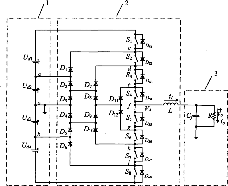
Figure 1 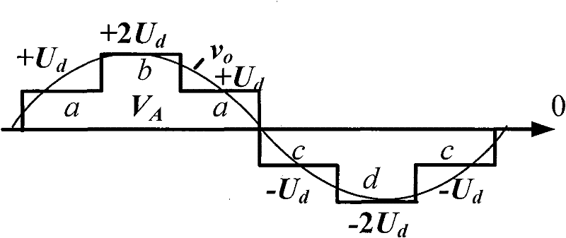
Figure 2 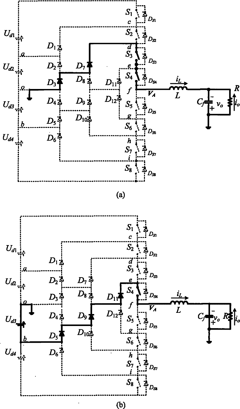
Figure 3
Abstract
Description
technical field
[0001] The invention relates to the technical field of control of a single-phase diode-clamped five-level half-bridge inverter. Background technique
[0002] With the development of society, the application of high-voltage and large-capacity inverters is becoming more and more extensive, and with the continuous improvement of input voltage levels, the limitations of the traditional two-level are becoming more and more obvious, first of all, it is limited by the withstand voltage of power electronic devices , In addition, EMI is large, and the harmonic content of the output voltage is large. In order to solve this problem, multilevel inverters have emerged, among which diode-clamped multilevel inverters are widely used because of their simple control and topology. There are also various control methods, but when these control methods are applied to bridge circuits, they all need to add a dead zone. The addition of the dead zone makes the output voltage of the...
Examples
Embodiment Construction
[0019] Such as figure 2 As shown, the half-bridge arm output voltage V A And the output voltage v obtained by filtering o Waveform, where the bridge arm outputs five levels: "+2U d ","+U d ", "0", "-U d " and "-2U d "(with the cathode of the second DC voltage source as the reference point). When the output voltage v o >0, the output level of the half-bridge arm is "0", "+U d "Switch between" (area a) or level "+U d ","+2U d "Switch between" (area b); when the output voltage v o d Switch between "(c area) or level"-U d ","-2U d " to switch between (zone d).
[0020] Output "+2U d " level, i L >0, such as image 3 (f), all power switches of the upper half-bridge arm are turned on, that is, S 1 , S 2 , S 3 and S 4 At the same time conduction, the current from U d1 Anode outflow, through S 1 , S 2 , S 3 , S 4 , the output filter inductor and filter capacitor flow into U d2 cathode; i L Figure 4 (c), all power switches are turned off, and the current flow...