
Alternating force based linear ultrasonic motor
A linear ultrasonic motor, alternating force technology, applied in the direction of generators/motors, piezoelectric effect/electrostrictive or magnetostrictive motors, electrical components, etc., can solve the tangential alternating force linear ultrasonic motor that has not yet been seen and other problems, to achieve the effect of simple structure, high efficiency and high speed
Patent Information
- Authority / Receiving Office
- CN · China
- Patent Type
- Patents(China)
- Current Assignee / Owner
- Publication Date
- 2012-09-26
- Estimated Expiration
- Not applicable · inactive patent
Smart Images
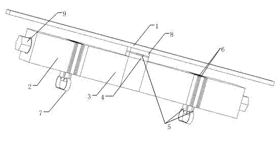
Figure 1 
Figure 2 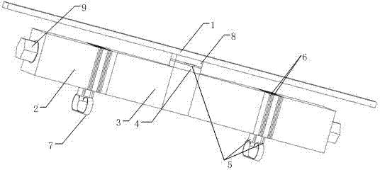
Figure 3
Abstract
Description
technical field
[0001] The invention relates to a linear ultrasonic motor based on alternating force and its working mode and electric excitation mode, belonging to the technical field of ultrasonic motors. Background technique
[0002] Ultrasonic motor is a new type of power output device that utilizes the inverse piezoelectric effect of piezoelectric ceramics and ultrasonic vibration. Compared with electromagnetic motors, it has the advantages of compact structure, low-speed high-torque, fast response (milliseconds), power-off self-locking, good position and speed control, no electromagnetic interference, and low-noise operation. It is used in aerospace, micro Machinery, robots, precision instruments, servo mechanisms, medical devices and other fields have broad application prospects.
[0003] Linear ultrasonic motors belong to a category of ultrasonic motors. According to the structure of the stator of the linear ultrasonic motor is a plate and a rod (or a combined stru...
Examples
Embodiment Construction
[0018] A linear ultrasonic motor based on alternating force such as figure 1 As shown, it includes a stator and a mover. It is characterized in that: the stator is mainly composed of two left and right Langevin vibrators butted along the center line, and each Langevin vibrator is composed of a front cover 3, a rear end cover 2, a piezoelectric The ceramic sheet 6 and the corresponding electrode sheet 5 are composed of a continuous cross-section rod structure whose section is tapered from the tail to the head as a whole. A piece of piezoelectric ceramic sheet 4 for the driving foot is pasted on the surface parallel to the longitudinal vibration surface of the vibrator at the joint of the vibrator, and an electrode sheet 5 and a piece of friction sheet 8 are pasted on the piezoelectric ceramic sheet 4 for the driving foot to form the driving foot. The mover is A linear guide rail 1 is arranged in a parallel structure with the above-mentioned stator and contacts each other at the...