
Coating technique of LED fluorescent powder
A coating process and phosphor technology, applied in the directions of coating, electrolytic coating, electrophoretic plating, etc., can solve the problem of direct coating of phosphors, and achieve the effect of good consistency, strong controllability and uniform light
Patent Information
- Authority / Receiving Office
- CN · China
- Patent Type
- Patents(China)
- Current Assignee / Owner
- Publication Date
- 2015-01-21
Smart Images
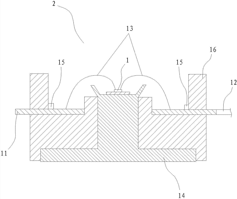
Figure 1 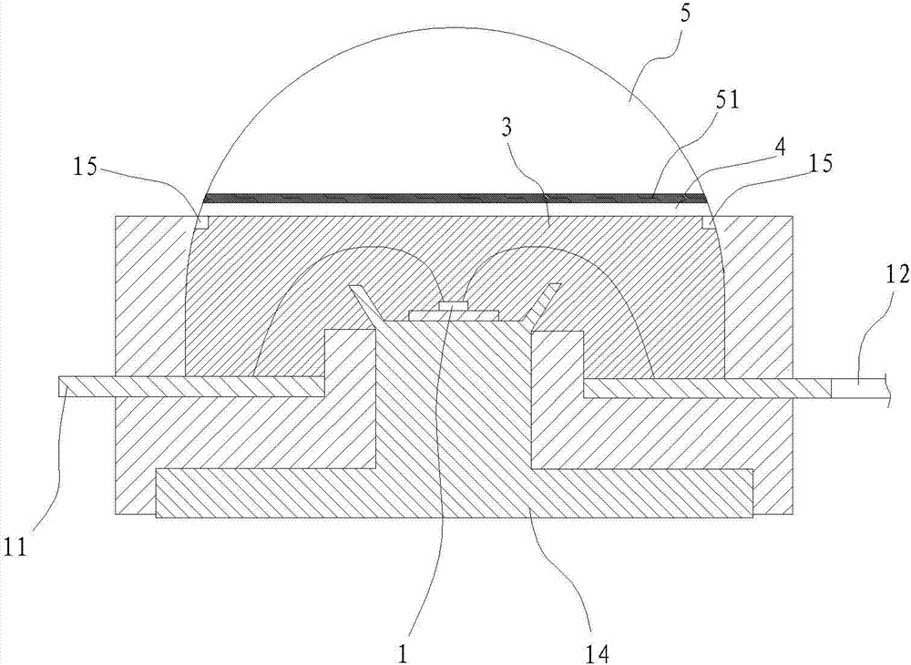
Figure 2 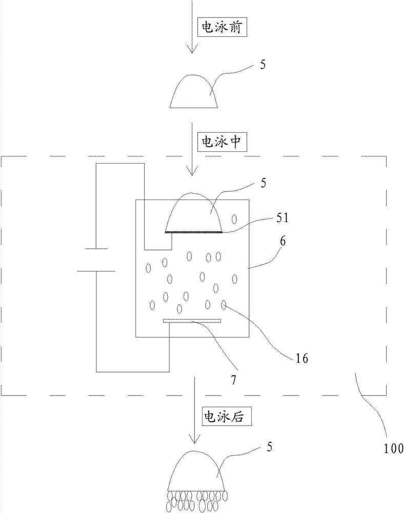
Figure 3
Abstract
Description
technical field
[0001] The present invention relates to LEDs (Light-Emitting Diodes, light-emitting diodes), in particular to an LED packaging structure excited by far-field. Background technique
[0002] There are many ways to achieve white light from LEDs, such as RGB chip combination, blue chip to excite phosphor, UV chip to excite phosphor, etc. Currently, the most commonly used method is to coat phosphor on blue or near-ultraviolet LED chips. White light reflection. Using the blue light (420nm-470nm) or near-ultraviolet light (370nm-410nm) emitted by the LED chip as the main spectrum, the phosphor absorbs the main spectrum and is excited to generate a sub-spectrum longer than the main spectrum wavelength, thereby converting to dual wavelength or Three-wavelength white light. In the above process, the packaging structure and process technology of fluorescent materials (phosphor powder) covering LEDs are the key technologies for white LEDs.
[0003] Phosphor powder is ...
Examples
Embodiment Construction
[0038] The present invention will be further described in conjunction with the accompanying drawings and specific embodiments.
[0039] The high-power LED bracket is now taken as a specific example to illustrate the LED phosphor coating process of the present invention. Such as figure 1 with figure 2 As shown, the LED packaging structure includes an LED chip 1 , a bracket 2 , a silica gel layer 3 , a phosphor layer 4 , and an optical lens 5 . The non-light-emitting surface of the optical lens 5 is provided with an ITO (Indium Tin Oxides, nanometer indium tin metal oxide) conductive layer 51 , and the outer surface of the optical lens 5 is in the shape of a free-form surface and has no conductive function.
[0040] The bracket 2 is provided with a cup and bowl for placing the LED chip 1, a positive conductive pin 11 and a negative conductive pin 12 leading out the positive and negative poles of the LED chip 1 through a wire 13, and a cover covering the positive conductive pi...