
Spare Wheel Protection and Lifting Fixtures
A technology of fixing device and mounting bracket, which is applied in the layout, transportation and packaging of spare tires, vehicle parts, etc., can solve the problems of unadjustable stroke, prone to abnormal noise, no locking feature, etc., and achieves reasonable transmission mechanism and smooth transmission. Stable and prevent overload damage
Patent Information
- Authority / Receiving Office
- CN · China
- Patent Type
- Patents(China)
- Current Assignee / Owner
- Publication Date
- 2015-10-21
Smart Images
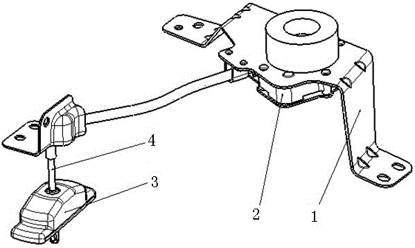
Figure 1 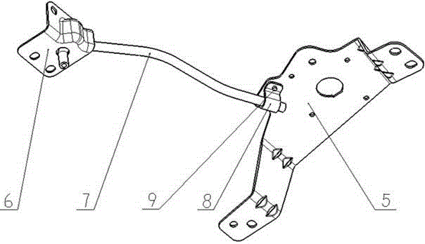
Figure 2 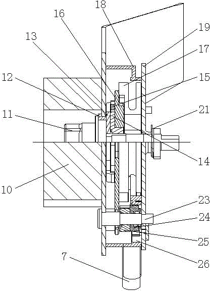
Figure 3
Abstract
Description
technical field
[0001] The invention relates to the field of external brackets for spare tires of automobiles, in particular to a spare tire protection and lifting and fixing device. Background technique
[0002] The spare tire protection and lifting fixing device for commercial vehicles is a device used for dismantling, lifting, fixing the spare tire and protecting the spare tire when the car is running. Most of the existing spare tire protection and lifting and fixing devices are chain-type and drive tube-welded drag frame mechanisms at present.
[0003] Among them, the chain structure generally directly uses the steel cable chain to fix the spare tire. Because there is no fixed moving track and no accurate pre-tightening device, the transmission of the mechanism is not stable during use, and there is no obvious locking feature, so it cannot provide locking protection. Time-consuming, laborious and noisy.
[0004] The bracket type mechanism welded by the transmission tub...
Examples
Embodiment 1
[0026] Such as figure 1 , 2 , 3, a spare tire protection and lifting fixture, including a mounting bracket assembly 1, a transmission mechanism assembly 2, a tray assembly 3 and a wire rope 4, the mounting bracket assembly 1 includes a large bracket 5, a small bracket 6 and a transmission tube 7, the large bracket 5 and the small bracket 6 are fixedly connected to the vehicle body, and the large bracket 5 and the small bracket 6 are fixedly connected through the transmission tube 7; the transmission mechanism assembly 2 is fixedly installed on On the large bracket 5, the main shaft 11 in the transmission mechanism assembly 2 is connected with a transmission disc 13, and the transmission disc 13 is connected to the inner toothed disc 17 through gear transmission, and the inner toothed disc 17 is provided with a wire groove. One end of the steel wire rope 4 is connected to the tray assembly 3, and the other end of the steel wire rope 4 passes through the transmission pipe 7 and...