
Subsection split phase automatic-passing system of electric railway and split phase automatic-passing method thereof
An automatic over-phase, electrified railway technology, applied in power lines, transportation and packaging, vehicle components, etc., can solve the problem that the current transformer cannot detect the train passing signal, reduce the train speed and capacity, and the train cannot receive current. , to achieve the effect of reliable uninterrupted power, automatic over-phase, simple structure and control, and fewer actions
Patent Information
- Authority / Receiving Office
- CN · China
- Patent Type
- Applications(China)
- Current Assignee / Owner
- Publication Date
- 2014-03-12
Smart Images
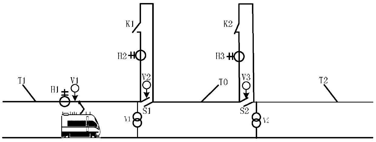
Figure 1 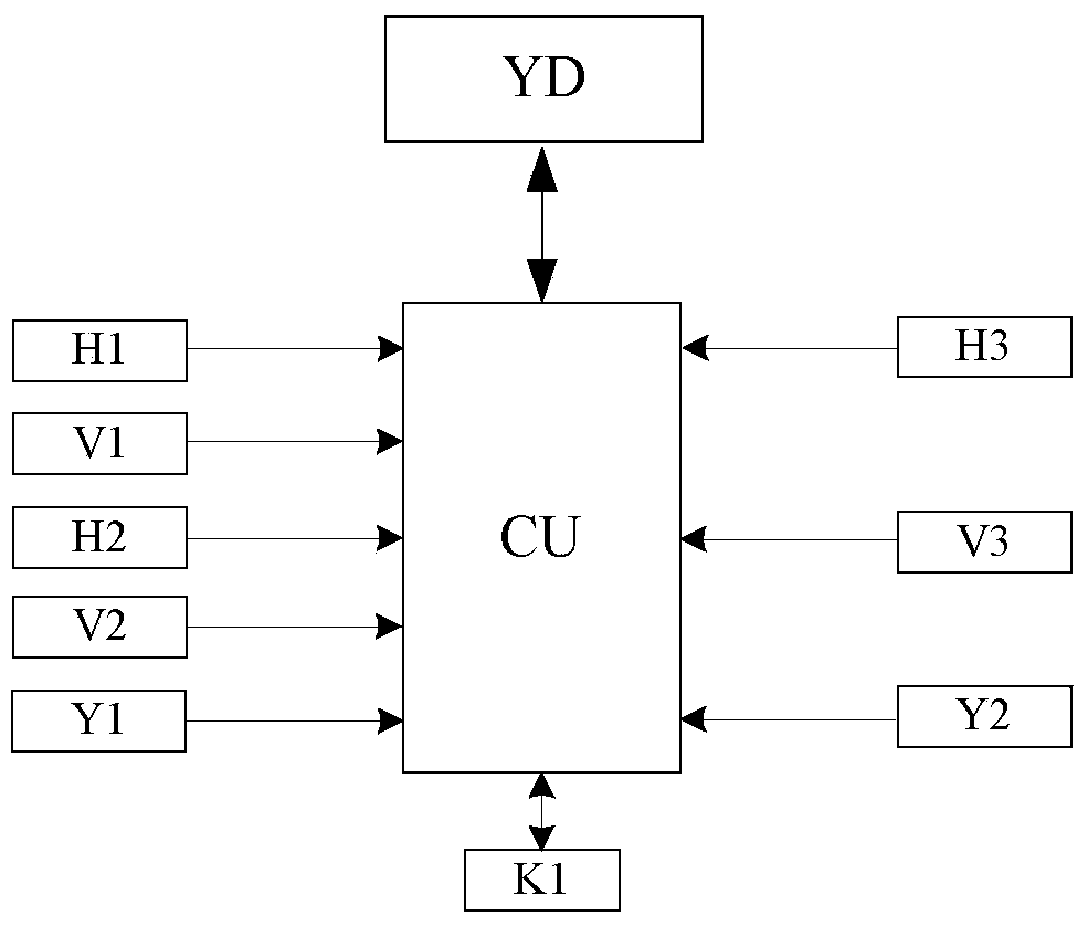
Figure 2 
Figure 3
Abstract
Description
technical field
[0001] The invention relates to an automatic phase separation system and an automatic phase separation method for electrified railway divisions. Background technique
[0002] my country's electrified railway generally adopts single-phase power frequency AC system. In order to make the three-phase load of the power system as balanced as possible, the electrified railway often adopts the scheme of alternating phase sequence and phase-separated partition power supply. The adjacent power supply intervals at the phase-separation partition are divided by air or insulators to form insulating electrical phase separation, referred to as electrical phase separation or phase separation.
[0003] In order to prevent electric locomotives from burning out catenary suspension components due to arcing through phase separation, and even causing accidents such as phase-to-phase short circuit, when the train is over-phase-splitting, the driver needs a series of manual operation...
Examples
Embodiment
[0036] figure 1 , 2 It shows that a specific embodiment of the present invention is an automatic phase separation system for electrified railway divisions, including catenary one T1, catenary two T2, and neutral section T0, and catenary one T1 passes through electric segment one S1 Connected with the neutral section T0, catenary two T2 is connected with the neutral section T0 through the electric section two S2, wherein: the catenary one T1 is connected in series with the current transformer one H1 near the electric section one S1; the current transformer two H2 and normally open switch one K1 are connected in series and then connected in parallel on electric segment one S1; current transformer three H3 and normally closed switch two K2 are connected in series and then connected in parallel on electric segment two S2; current transformer one H1 Pantograph Detector 1 V1 is installed on the pillar of S1, Pantograph Detector 2 V2 is installed on the pillar at Electric Section 1 ...