
Enhanced electroluminescent sign
a technology of electroluminescent signs and enhanced light, applied in the direction of illuminated signs, display means, instruments, etc., can solve the problem of increased visible speckle contrast on the sign, and achieve the effect of improving the visible speckle contrast, efficient direction, and low cos
Patent Information
- Authority / Receiving Office
- US · United States
- Patent Type
- Applications(United States)
- Current Assignee / Owner
- Publication Date
- 2006-09-28
- Estimated Expiration
- Not applicable · inactive patent
Smart Images
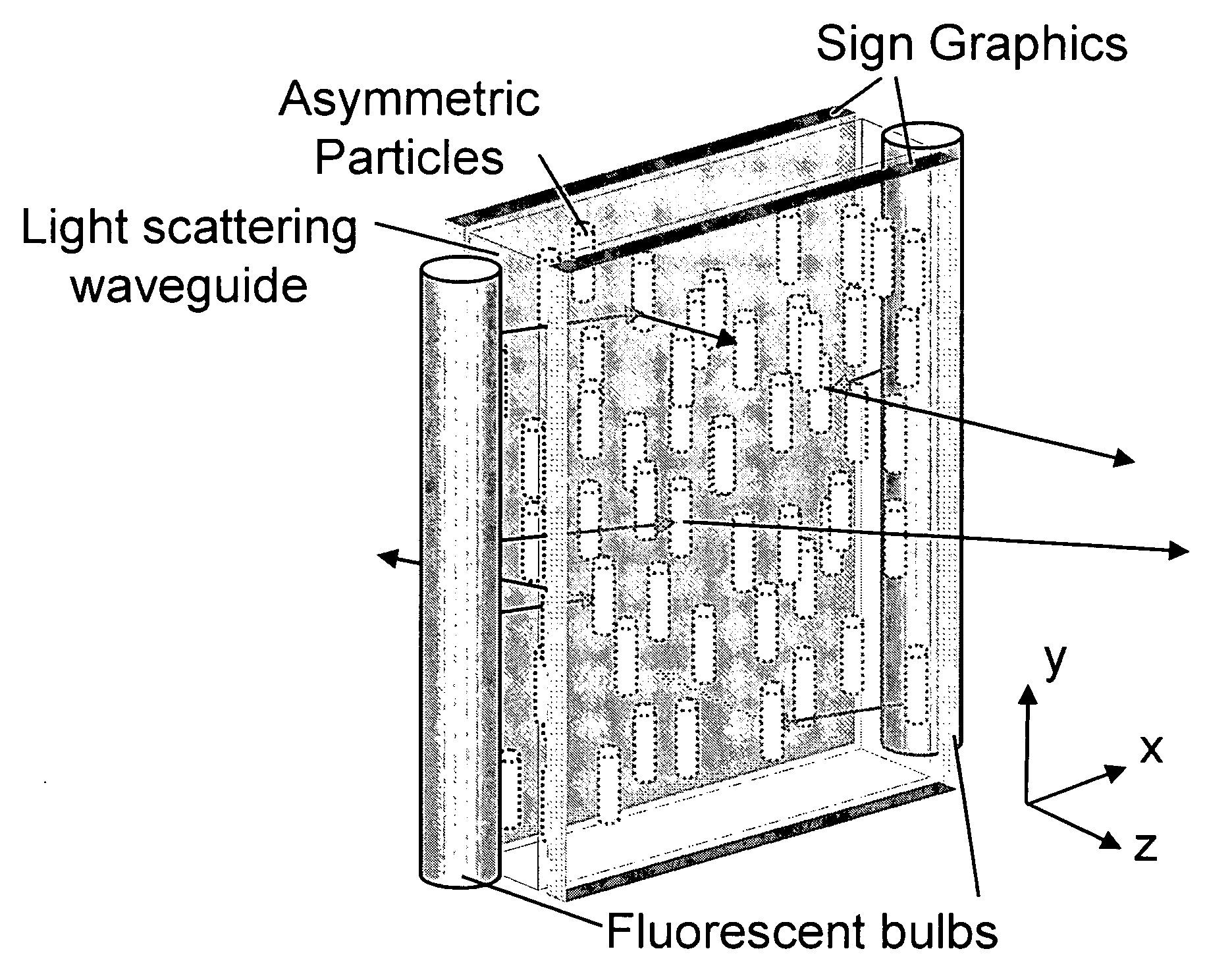
Figure 1 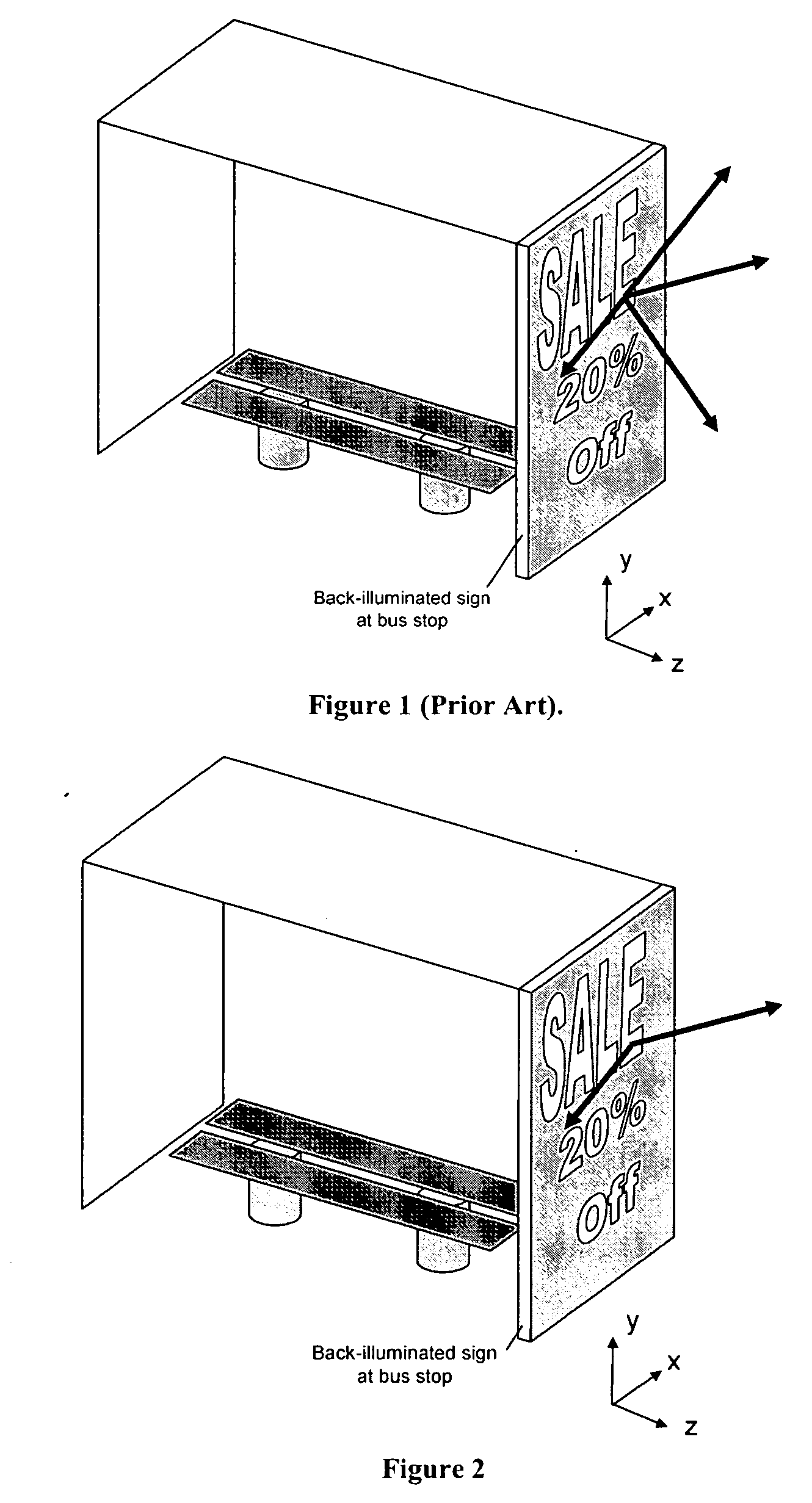
Figure 2 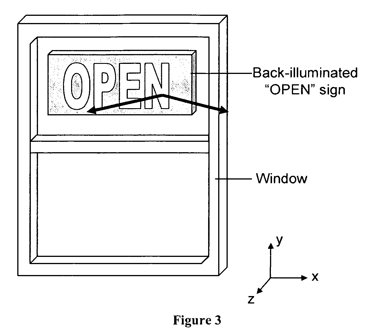
Figure 3
Abstract
Description
RELATED APPLICATIONS
[0001] This application claims the benefit of priority under 35 U.S.C. 119(e) to copending U.S. Provisional Application No. 60 / 628,769, filed on Nov. 17, 2004, the entire contents of which is incorporated herein by reference.FIELD OF THE INVENTION
[0002] The invention generally relates to electroluminescent signs or other devices capable of displaying images or indicia wherein light is emitted such that indicia can be visually recognized. The invention also relates to the components contained within the electroluminescent signs or devices. BACKGROUND OF THE INVENTION
[0003] Electroluminescent signs such as neon, traditional fluorescent backlit signs and channel lettering typically direct light into large angles in the horizontal and vertical directions. In many cases, the light does not need to be directed in to certain angular directions because the sign is not normally viewed from that direction. For example, most signs are typically viewed in the horizontal d...
Examples
example 1
[0108] An enhanced electroluminescent sign in accordance with the present invention, i.e., as illustrated in FIG. 11, has increased spatial luminance uniformity, increased optical efficiency and is of low production cost. A 16″×20″ direct-lit light box sign (Ultra Thin Light Up Display from Bowman Displays) is used as a benchmark for comparison with the enhanced electroluminescent sign of this invention. The spatial luminance uniformity is measured at 0.5 cm intervals on either side of a region directly above the T8 fluorescent lamp in the white light box with the included standard symmetric diffuser film (Sample STANDARD) with a Minolta CS-100 spectrophotometer. The angular luminance profile is measured at a location directly above a fluorescent bulb with the standard symmetric diffuser film with a Minolta CS-100 luminance and tristimulous spot meter at varying 5 degree angular positions.
[0109] A light scattering film with anisotropic scattering profile was prepared by blending an...
example 2
[0111] An enhanced electroluminescent sign in accordance with the present invention can be produced as described in FIG. 8, that has increased spatial luminance uniformity, increased optical efficiency, reduced speckle and lower costs of production. This is due in part to the use of the volumetric anisotropic scattering region within the waveguide to more efficiently control the light scattering. A light diffusing waveguide containing light scattering particles in a host matrix material is created by extruding, casting or coating, the mixture containing particles. The particle chosen may be a polystyrene bead of diameter 5 μm in the minor axis and 20 μm in the major axis dispersed at 10% concentration in a host matrix of acrylic. Other choices of particles and host matrix may provide equivalent performance. Asymmetry and alignment of the asymmetry can be created by stretching or extrusion processes. The resulting material suitable for waveguiding light contains asymmetric particles ...
example 3
[0112] An enhanced electroluminescent sign, in accordance with the present invention, can be produced as described in FIG. 11, that is designed to have increased spatial luminance uniformity, increased optical efficiency, reduced speckle and lower costs of production. This is due in part to the use of the volumetric anisotropic scattering element more efficiently controls the light scattering. A light diffusing film containing light scattering particles in a host matrix material is created by extruding, casting or coating, the mixture containing particles. The particle chosen may be a polystyrene bead of diameter 5 μm in the minor axis and 20 μm in the major axis dispersed at 10% concentration in a host matrix of acrylic. Other choices of particles and host matrix can provide equivalent performance. Asymmetry and alignment of the asymmetry can be created by stretching or extrusion processes. The resulting film suitable for diffusing light contains asymmetric particles and is placed ...