
A laser ranging optical system and its main wave signal sampling method
An optical system, laser ranging technology, applied in radio wave measurement systems, measurement devices, electromagnetic wave re-radiation and other directions, can solve the problems of reduced measurement accuracy, circuit delay differences, system complexity, etc., to achieve high measurement accuracy, Low cost and damage prevention effect
Patent Information
- Authority / Receiving Office
- CN · China
- Patent Type
- Patents(China)
- Current Assignee / Owner
- Publication Date
- 2018-06-01
- Estimated Expiration
- Not applicable · inactive patent
Smart Images
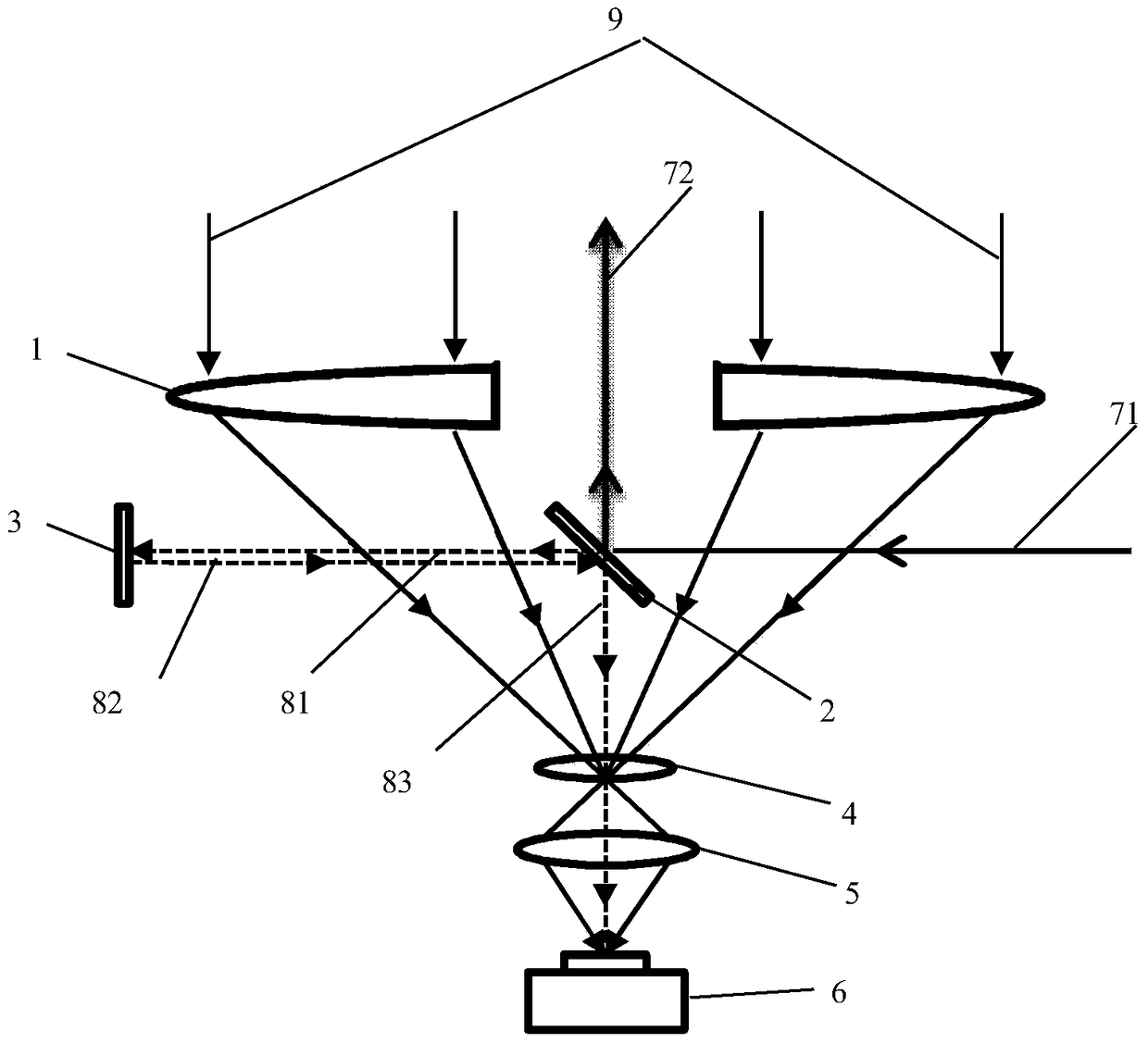
Figure 1 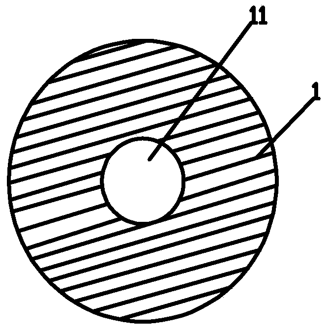
Figure 2
Abstract
Description
technical field
[0001] The invention belongs to the technical field of laser ranging, and in particular relates to a laser ranging optical system and a main wave signal sampling method thereof. Background technique
[0002] Laser ranging refers to a measurement technology that uses a laser beam directed at a ranging target to measure the distance to a target. The laser beam is emitted by the laser light source, most of the laser beam is emitted to the ranging target through the laser emission system, and is reflected by the ranging target and returned as an echo laser beam; the echo laser beam is received by a photodetector as an echo laser beam. A small part of the laser beam converges to the photodetector as the main wave signal; the measured distance is obtained through the comparison and analysis of the echo signal and the main wave signal, combined with the ranging equation.
[0003] In the existing laser ranging system, there are two design schemes for the optical sys...
Examples
Embodiment 1
[0029] like figure 1 As shown, a laser ranging optical system includes a receiving objective lens 1, a field lens 4, a transforming objective lens 5 and a photodetector 6 arranged in sequence, and the surfaces of the receiving objective lens 1, the field lens 4 and the transforming objective lens 5 are all coated with a pair of A film with high transmittance of the laser beam 71 , the photodetector 6 is provided with a photosensitive surface that responds to the laser beam 71 , and the photosensitive surface is set at the focal position of the conversion objective lens 5 .
[0030] The receiving objective lens 1 is used for receiving the receiving beam 9, the field lens 4 converges the sampling beam 83 and the receiving beam 9 that deviate from the focal point of the receiving objective lens 1, and the transforming objective lens 5 is used for changing the sampling beam 83, the receiving beam 9. The spot size of the receiving beam 9 is matched with the size of the photosensiti...
Embodiment 2
[0033] like figure 1 As shown, the receiving objective lens 1, the field lens 4 and the transforming objective lens 5 are arranged in a coaxial structure, the field lens 4 is located at the focal point of the receiving objective lens 1, and the receiving objective lens 1 and the field lens 4 are arranged between There is a reflector one 2, and the reflector one 2 adopts the edge clamping method, and its center is located on the optical axis of the receiving objective lens 1, and the reflector one 2 and the optical axis of the receiving objective lens 1 are arranged at 45° to promote the emission The optical path and the receiving optical path are coaxial.
[0034] One side of the reflecting mirror 2 is provided with a reflecting mirror two 3, the reflecting mirror two 3 is arranged in parallel with the optical axis of the receiving objective lens 1, and the centers of the reflecting mirror one 2 and the reflecting mirror two 3 are located on the same straight line. It is perp...
Embodiment 3
[0037] like Figure 1-2 As shown, the laser beam 71 is a pulsed laser, the power is P, the beam diameter is 20mm, the pulse width is 10ns, and the wavelength is 1064nm. T1=0.2%, the reflectivity of the mirror 23 to the laser beam 71 is R2=90%, the aperture of the through hole 11 is 25mm, and the method for sampling the main wave signal of the laser ranging optical system in this embodiment, It includes the following steps:
[0038] (1) The laser beam 71 is incident on the mirror 1 2 at an incident angle of 45°. The incident side of the laser beam 71 is different from the position where the mirror 2 3 is located. A part of the laser beam 71 is blocked by the mirror 1 2 is reflected and penetrated through the through hole 11 as the emission beam 72; the other part of the laser beam 71 is transmitted through the mirror 1 2 as the transmission beam 81, and the power of the transmission beam 81 is P×0.2%, that is, P× (1-99.8%);
[0039] (2) The transmitted light beam 81 is incid...