
Defoaming method for thickener in beneficiation plant and device implementing same
A technology of thickeners and concentrators, which is applied to the device of the defoaming method and the field of eliminating floating foam in the thickener, which can solve the problems of failure and impact of foaming agents, achieve effective defoaming effect, low energy consumption, and reduce fineness The effect of mine loss
Patent Information
- Authority / Receiving Office
- CN · China
- Patent Type
- Applications(China)
- Current Assignee / Owner
- Publication Date
- 2015-12-23
- Estimated Expiration
- Not applicable · inactive patent
Smart Images
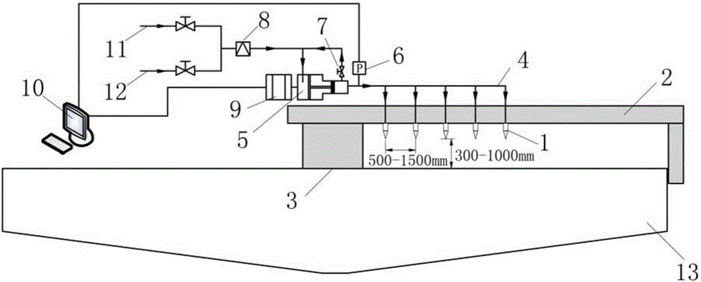
Figure 1
Abstract
Description
technical field
[0001] The invention relates to a defoaming method, in particular to a method for eliminating floating foam in a thickener in a mineral processing plant. The invention also relates to a device for realizing the defoaming method of the thickener of the ore dressing plant. Background technique
[0002] Thickeners (also known as thickeners) are usually used in concentrators to concentrate flotation concentrates and medium ore foams. Because the ore pulp contains a relatively high concentration of agents with foaming properties, the generated foams are stable and cannot burst in time. Accumulate gradually, and form a spongy floating foam layer after dehydration and solidification, with a thickness of 100mm-500mm. The foam layer contains a large amount of concentrate, which cannot be effectively settled and flows away with the overflow water, causing economic losses to the concentrator. For example, the thickness of the foam layer of a thickener in a tungsten ore...
Examples
Embodiment 1
[0036] The foam defoaming test of a 38m thickener in Henan Luanchuan Tungsten Ore Concentrator was carried out by adopting the method described in the present invention. Before the test, the thickness of the foam layer of the concentrator thickener was about 500mm, the solid content of the surface foam was about 60%, the solid content of the overflow water was about 7%, and the loss of tungsten in the overflow water was about 5%. During the test, according to figure 1As shown, nine high-pressure atomizing nozzles 1 are sequentially arranged on the thickener arm 2 of the thickener 13 along the 3 ends of the central rotating shaft, and the distance between adjacent high-pressure atomizing nozzles 1 is 1000mm. Change and adjust up and down, the distance is always kept at 500mm, and the water outlet form of the high-pressure atomizing nozzle 1 is adjusted to be cone-shaped mist, and the cone angle is 15°. The speed of the variable frequency motor 9 is adjusted by the frequency co...
Embodiment 2
[0038] The defoaming test of two 20m thickeners in Hunan Chenzhou fluorite ore dressing plant was carried out by using the method described in the present invention. Before the test, the thickness of the foam layer of the concentrator thickener was about 300mm, the solid content of the surface foam was about 57%, the solid content of the overflow water was about 6%, and the loss of fluorite in the overflow water was about 6%. During the test, according to figure 1 As shown, on the thickener arm 2 of the thickener 13, five high-pressure atomizing nozzles 1 are sequentially arranged along the 3 ends of the central rotating shaft, and the distance between adjacent high-pressure atomizing nozzles 1 is 1000mm. Change and adjust up and down, the distance is always kept at 500mm, and the water outlet form of the high-pressure atomizing nozzle 1 is adjusted to be cone-shaped mist, and the cone angle is 15°. The speed of the variable frequency motor 9 is adjusted by the frequency conv...
Embodiment 3
[0040] The defoaming test of a 32m thickener in Hunan Shizhuyuan polymetallic mineral processing plant was carried out by adopting the method of the present invention. Before the test, the thickness of the foam layer of the concentrator thickener was about 300mm, the solid content of the surface foam was about 61%, the solid content of the overflow water was about 8%, the loss of tungsten in the overflow water was about 6%, and the tin was about 11%. During the test, according to figure 1 As shown, eight high-pressure atomizing nozzles 1 are sequentially arranged on the thickener arm 2 of the thickener 13 along the 3 ends of the central rotating shaft, and the distance between adjacent high-pressure atomizing nozzles 1 is 1000mm. Change and adjust up and down, the distance is always kept at 500mm, and the water outlet form of the high-pressure atomizing nozzle 1 is adjusted to be cone-shaped mist, and the cone angle is 15°. The speed of the variable frequency motor 9 is adjus...