
Visible light communication subcarrier multiplexing clock synchronization receiving device
A technology of subcarrier multiplexing and visible light communication, applied in the field of visible light communication, can solve problems such as jumping, inability to provide voltage, clock phase jitter, etc., and achieve the effect of simple device structure and high communication reliability
Patent Information
- Authority / Receiving Office
- CN · China
- Patent Type
- Applications(China)
- Current Assignee / Owner
- Publication Date
- 2016-01-13
Smart Images
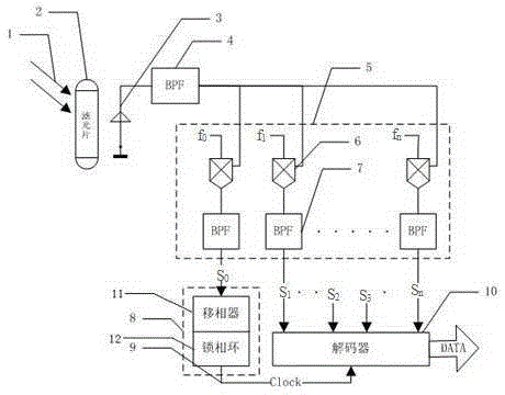
Figure 1 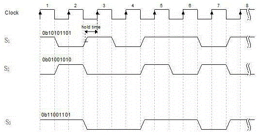
Figure 2
Abstract
Description
technical field
[0001] The present invention relates to the field of visible light communication, in particular to a visible light communication subcarrier multiplexing clock synchronization receiving device. Background technique
[0002] LED has good modulability, and LED can be used to transmit information by high-speed bright and dark flickering, so that LED light source has communication capability. As a communication system, the clock at the receiving end must be consistent with that at the transmitting end in order to recover data accurately. Since the visible light communication system has only one physical channel, the clock cannot be sent separately, so a method of recovering the clock at the receiving end is required. A common method of recovering the clock at the receiving end is to transmit an obvious clock mark to the receiving end at the sending end. This time mark is included in the data packet, and a voltage jump for clock recovery is generated during the enc...
Examples
Embodiment
[0021] Example: such as figure 1 As shown, a visible light communication subcarrier multiplexing clock synchronization receiving device includes a photodetector 3 and a demultiplexer 5 electrically connected to each other, and the demultiplexer 5 is electrically connected to a clock generator 8 and a decoder 10 respectively. , the clock generator 8 is electrically connected to the decoder 10, the photodetector 3 is used to convert the optical carrier signal from the transmitting end into a multiplexed subcarrier signal, and the demultiplexer 5 is used to multiplex The sub-carrier signal is separated into multiple sub-carrier signals, the clock generator 8 is used to restore the sub-carrier signal to a local clock signal, and the decoder 10 is used to decode the sub-carrier signal and output data.
[0022] This embodiment also includes a filter device 2, which is used to filter stray light in the optical carrier signal 1 from the transmitting end, and improve the signal-to-nois...