

Multi-stroke realizing circuit and multi-stroke control method for circuit breakers
A circuit breaker, multi-stroke technology, applied in the direction of protection switch operation/release mechanism, etc., can solve the problem of easy burning of circuit breaker closing/opening coils, etc., and achieve the effect of improving the closing success rate, ensuring maximum safety, and avoiding losses
Patent Information
- Authority / Receiving Office
- CN · China
- Patent Type
- Applications(China)
- Current Assignee / Owner
- Publication Date
- 2016-01-20
Smart Images
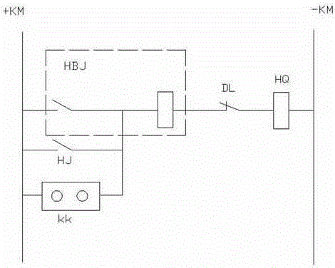
Figure 1 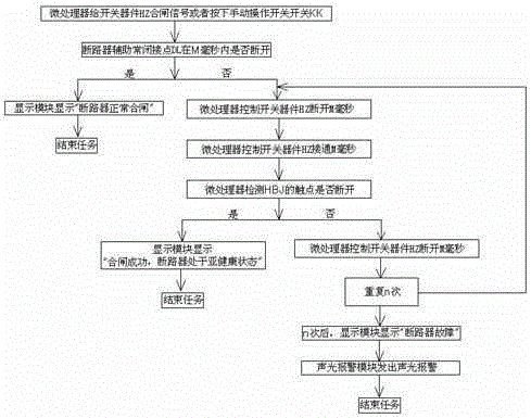
Figure 2 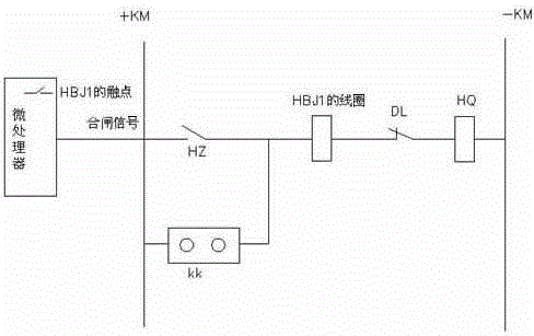
Figure 3
Abstract
Description
technical field
[0001] The invention relates to the protection field of distribution substation devices, in particular to a circuit breaker multi-stroke realization circuit and a control method. Background technique
[0002] In order to prevent damage to the contacts of the opening and closing relays during the process of disconnecting the operating current, the traditional opening and closing control circuits are equipped with current self-holding coils. Since the principles of the opening and closing control circuits are the same, we use the closing circuit As an example to explain the principle; figure 1 The closing circuit shown includes microprocessor, positive control bus +KM, negative control bus -KM, current self-holding coil HBJ, circuit breaker auxiliary normally closed contact DL, closing relay HJ, manual closing operation switch KK and closing Brake coil HQ, the output terminal of the microprocessor is connected with the closing relay HJ, which is used to contro...
Examples
Embodiment Construction
[0022] Such as figure 2 with image 3 As shown, the circuit breaker multi-stroke implementation circuit of the present invention includes a microprocessor, positive control bus +KM, negative control bus -KM, current relay HBJ, circuit breaker auxiliary normally closed contact DL, closing coil HQ and The manual closing operation switch KK also includes the switching device HZ;
[0023] The switching device HZ, the current relay HBJ, the auxiliary normally closed contact DL of the circuit breaker and the closing coil HQ are connected in series between the positive control bus +KM and the negative control bus -KM, the manual closing operation switch KK is connected in parallel at both ends of the switching device HZ, the switch The first end of the device HZ is connected to the output end of the microprocessor, and the contact of the current relay HBJ is connected to the input end of the microprocessor; the switching device HZ adopts an IGBT or a power triode, and the IGBT is a...