
Ducted power plant and aircraft
A technology of a power unit and a drive unit, applied in the field of aircraft, can solve the problems of shortened life, slow response speed of speed increase, complicated control system, etc., and achieve the effects of extending service life, speeding up the device quickly, and shortening the response time.
Patent Information
- Authority / Receiving Office
- CN · China
- Patent Type
- Patents(China)
- Current Assignee / Owner
- Publication Date
- 2017-10-17
Smart Images
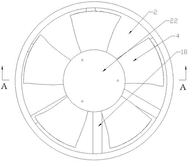
Figure 1 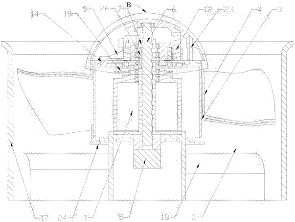
Figure 2 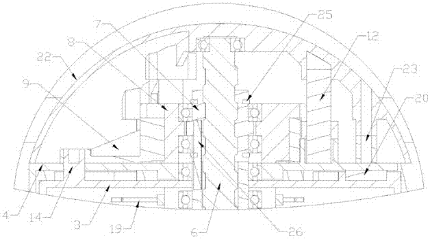
Figure 3
Abstract
Description
technical field
[0001] The invention relates to the field of aircraft, in particular to a power device with a duct and an aircraft using the duct power device. Background technique
[0002] The ducted power unit equipped on the aircraft generally includes ducts, rotors and motors coaxially arranged in the ducts, and the motors can also be arranged on the periphery of the ducts and drive the rotors to rotate through the drive shaft device to achieve normal work in the ducts.
[0003] In the prior art, the ducted power device usually achieves the purpose of increasing the rotation speed of the rotor and thus the flight speed by increasing the power of the motor. For example, the Chinese patent application whose publication number is CN 104401480 A discloses a ducted tilting aircraft. It is recorded in this patent application that the aircraft includes a fuselage, and a duct is provided on the fuselage, and a ducted propeller is installed in the duct. This solution increases ...
Examples
Embodiment Construction
[0045] Example of Ducted Power Plant
[0046] Such as figure 1 with Figure 12 As shown, the present invention includes a duct 2, a driving device 1, a first rotor 3, a second rotor 4, a top cover 22, a second rotating member 8 and a first rotating member 9 connected to a threaded bush 7 through a bearing. In the present invention, the driving device 1 is a motor 1 . Such as figure 2 As shown, the duct 2, the first rotor 3 and the second rotor 4 are coaxially arranged. The second rotor 4 can rotate relative to the first rotor 3 around the co-axis through a separation mechanism. Wherein the first rotor 3 and the second rotor 4 belong to the rotor of the whole power plant. Such as Figure 9 As shown, a connecting ring 24 is installed on the bottom of the second rotor 4, and the connecting ring 24 is used to prevent the rotor from vibrating in the axial direction, so as to prevent the two rotors from colliding with each other and being damaged due to vibration. Motor 1 is...