

Two-way non-reverse overrunning clutch
An overrunning clutch and non-return stop technology, applied to one-way clutches, clutches, mechanical equipment, etc., can solve the problems of inconvenient maintenance and short service life of two-way clutches, and achieve reliable operation, improved mechanical transmission efficiency, and simple structure Effect
Patent Information
- Authority / Receiving Office
- CN · China
- Patent Type
- Patents(China)
- Current Assignee / Owner
- Publication Date
- 2017-12-29
Smart Images
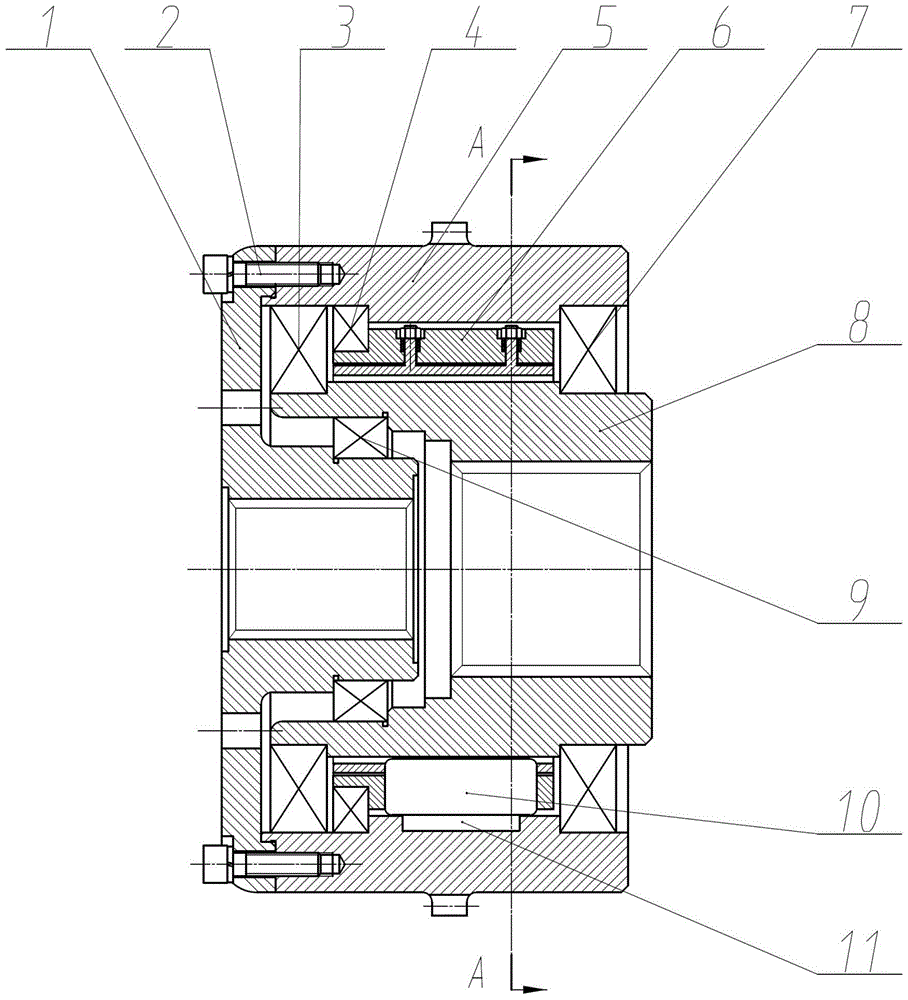
Figure 1 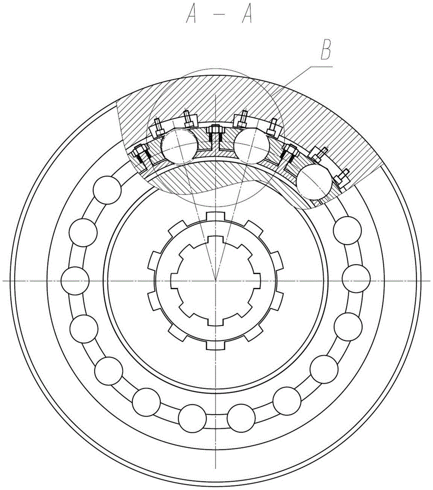
Figure 2 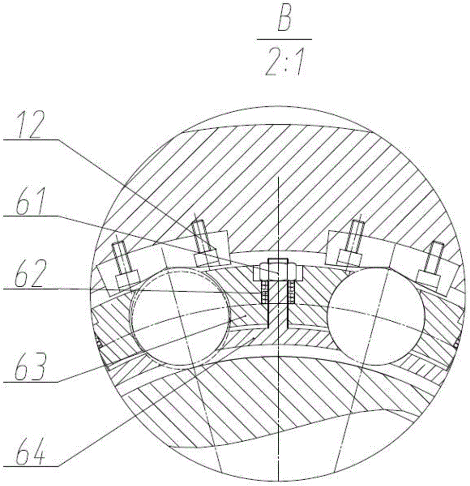
Figure 3
Abstract
Description
technical field
[0001] The invention belongs to a transmission device of a power device, and in particular relates to a bidirectional non-backstop overrunning clutch. It is used in the transmission shafting of the power plant of various naval ships. It is also suitable for the transmission shafting of the combined power plant of the ship. Background technique
[0002] In the current field of combined power transmission of Chinese ships, the clutch is mainly used to realize the combination and disengagement of the power device and the actuator. However, when the two powers transmit power at different speeds, how to perform functions such as two-way combination and two-way separation, and how the two do not affect each other when different power devices transmit power independently. With the current existing clutch, it is difficult to realize. Currently commonly used clutches mainly have three structural forms: friction plate clutches, wedge-shaped one-way clutches, and rol...
Examples
Embodiment Construction
[0015] like Figure 1-3 As shown, the present invention will be further described through specific embodiments below.
[0016] A two-way non-reverse overrunning clutch, the lower cover plate 1 of the clutch is connected with the outer race 5 through the screw a2. The wedge block 11 is fixed on the outer race 5 by the screw b12. Furthermore, the outer race 5 and the cage outer ring 63 are coupled through the ball bearing b4. The rollers 10 are set in the roller grooves of the cage assembly 6, and two small shafts with thread protrude between every two roller grooves of the inner ring 64 of the cage, and the small shafts pass through the holes of the outer ring 63 of the cage. out. A spring 62 is sheathed on the small shaft, and the force of the spring 62 is adjusted by a nut 61 , so that the cage outer ring 63 and the cage inner ring 64 are close to each other. The inner race 8 is connected with the outer race 5 through two ball bearings a3 and b7, and there is a tapered ro...