
A device and method for detecting water body turbidity based on underwater observation network
A detection device and observation network technology, applied in the direction of measuring devices, instruments, scientific instruments, etc., to achieve the effect of automation and intelligence
Patent Information
- Authority / Receiving Office
- CN · China
- Patent Type
- Patents(China)
- Current Assignee / Owner
- Publication Date
- 2018-11-02
Smart Images
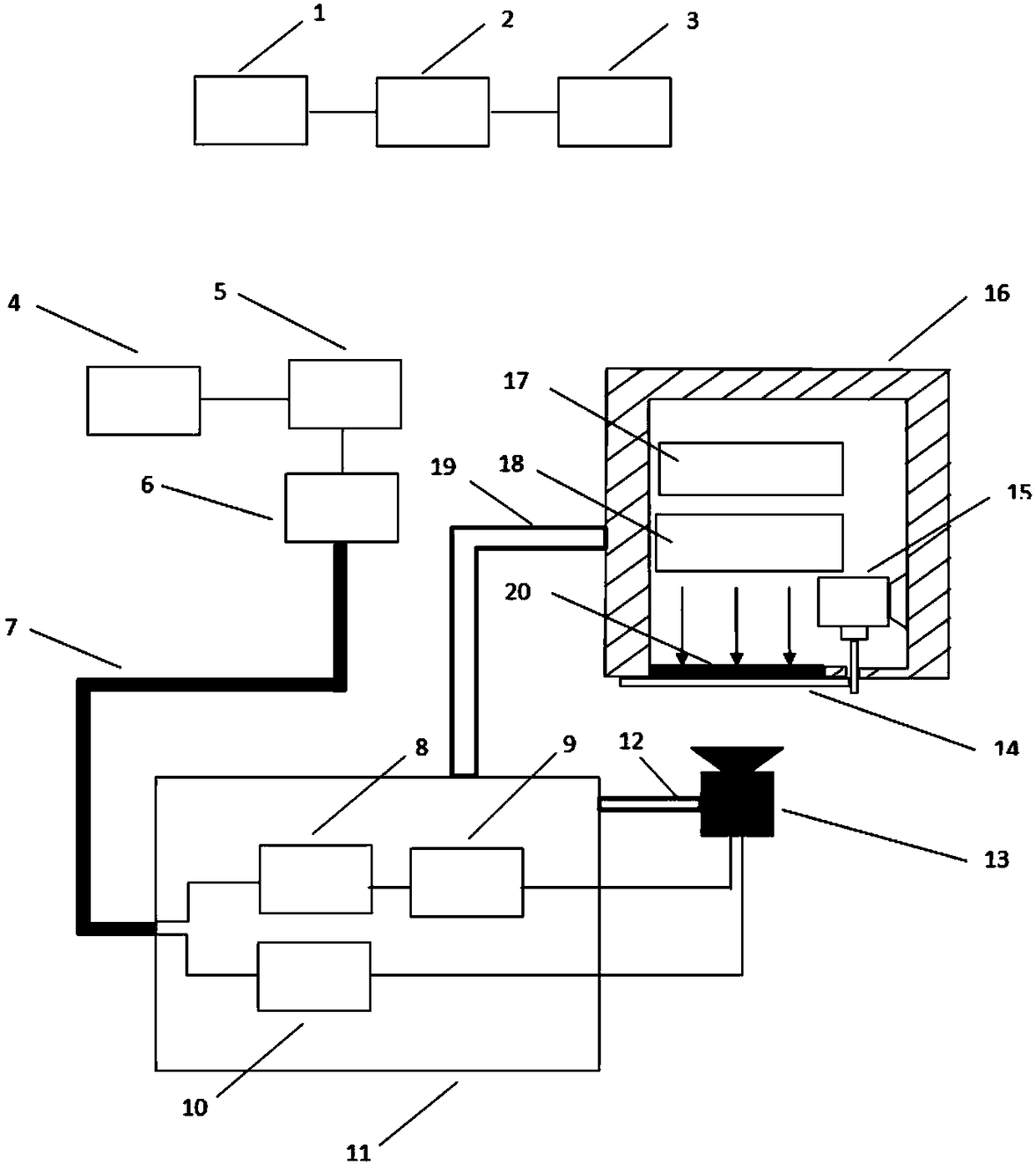
Figure 1 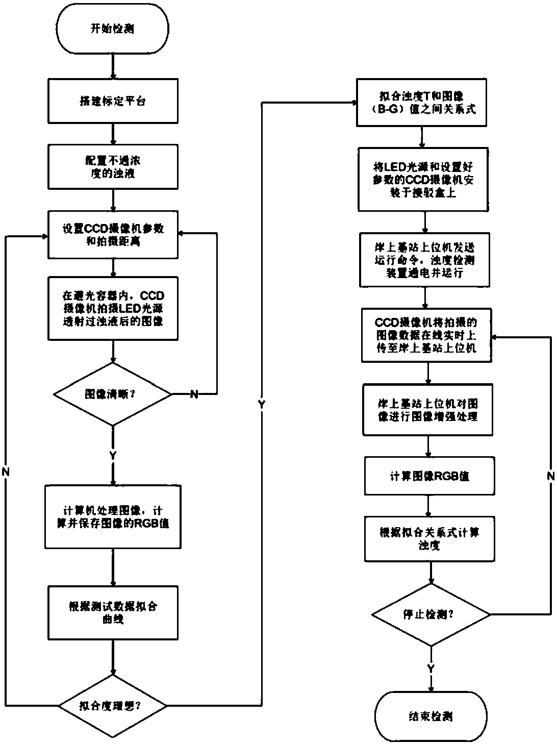
Figure 2
Abstract
Description
technical field
[0001] The invention designs a water body turbidity detection device and method based on an underwater observation network, belonging to the field of underwater observation networks. Background technique
[0002] The traditional water quality research methods can only observe the lake from the ground or the water surface by boat. With the development of satellite remote sensing technology, the water body can also be observed from the air, but these methods can only get sporadic data on the water body surface. The underwater observation network is composed of cables laid on the bottom of the water, an optical fiber network, and various instruments and equipment on the network. It overcomes the problems of equipment power supply and communication, and can realize continuous three-dimensional observation of water bodies.
[0003] The CCD image sensor was invented in the 1870s, which can convert optical images into digital signals. After decades of development, t...
Examples
Embodiment Construction
[0029] The present invention will be described in further detail below in conjunction with the accompanying drawings.
[0030] refer to figure 1 , 2 , a water turbidity detection device based on an underwater observation network of the present invention, comprising: a calibration subsystem, a light source subsystem, an image acquisition subsystem, and an image processing subsystem; wherein:
[0031] The calibration subsystem includes a computer 1, a video server 2, and a light-proof container 3. The video server 2 is connected to the computer 1, and all turbidity calibrations are carried out in the light-proof container 3;
[0032] The light source subsystem includes a light source closed cavity 16 and a monochromatic LED light source 18 placed in the cavity, a stepping motor 15, an LED lamp and a motor control circuit 17, and the cavity is provided with an observation window 20 made of transparent glass, A wiper 14 is arranged outside the observation window 20, and the wipe...