
A Drilling Tool Using Turbine to Realize Rotating Impact
A technology for drilling tools and turbine rotors, which is applied to drilling equipment, driving devices for drilling in wellbore, earth-moving drilling, etc. Improve energy utilization and ensure the effect of effective transmission
Patent Information
- Authority / Receiving Office
- CN · China
- Patent Type
- Patents(China)
- Current Assignee / Owner
- Publication Date
- 2018-06-01
Smart Images
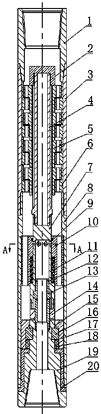
Figure 1 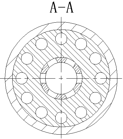
Figure 2 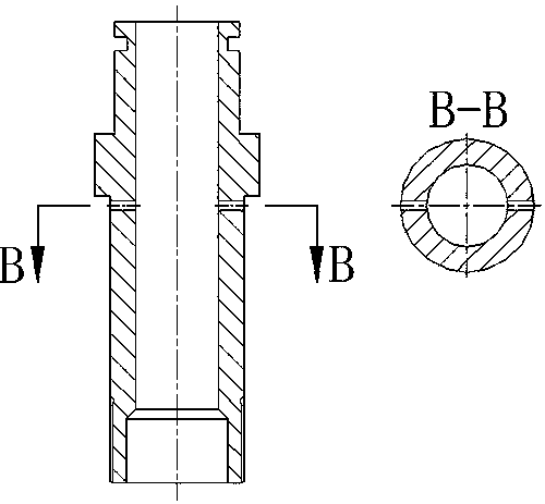
Figure 3
Abstract
Description
technical field
[0001] The invention relates to a drilling tool for oil and gas drilling, geological drilling and other fields, which utilizes a turbine to realize rotary impact. Background technique
[0002] With the continuous increase of oil consumption, shallow oil fields can no longer meet the needs of human beings, and oil extraction is developing in the direction of deep wells and ultra-deep wells with large oil reserves, complex geology and difficult drilling. What conventional drilling mainly adopts now is to utilize the rotary table to drive the drill string to rotate the drill bit to break the drilling method (rotary drilling) of the rock at the bottom of the hole. However, when drilling deep and ultra-deep wells, the rock is often hard and the working conditions are complicated. Using traditional methods often leads to problems such as low rock-breaking efficiency of the drill bit and a decrease in the mechanical speed of penetration.
[0003] At present, impact...
Examples
Embodiment Construction
[0013] The present invention will be further described below in conjunction with accompanying drawing:
[0014] See attached figure 1 , a drilling tool that uses a turbine to achieve rotary impact, consisting of an upper joint 1, a nut 2, an upper casing 3, a turbine shaft 4, a turbine rotor 5, a turbine stator 6, a central tube 7, a lower casing 8, and a sleeve seal Ring 9, sleeve 10, disc spring 11, piston sealing ring 12, piston 13, hammer 14, clamping sleeve sealing ring 15, half ring 16, clamping sleeve 17, O-ring sealing ring 18, anvil 19 and Bafang The sleeve 20 is composed of the upper joint 1, the upper casing 3 and the lower casing 8, which are threaded in sequence, and after being fixed, a cavity is formed inside, and the cavity is followed by a nut 2, a turbine shaft 4, and a center Pipe 7, hammer 14, anvil 19; the upper end of the turbine shaft 4 is threadedly connected with the nut 2, and the lower end is threadedly connected with the center pipe 7; the turbine ...