
Space relative displacement change monitoring system and method
A relative displacement and change monitoring technology, applied in the field of electronic information, can solve the problems of unable to solve the accumulation of displacement calculation errors, unable to quantify distance tracking, and high power consumption
Patent Information
- Authority / Receiving Office
- CN · China
- Patent Type
- Applications(China)
- Current Assignee / Owner
- Publication Date
- 2016-10-26
Smart Images
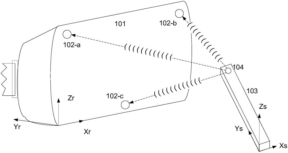
Figure 1 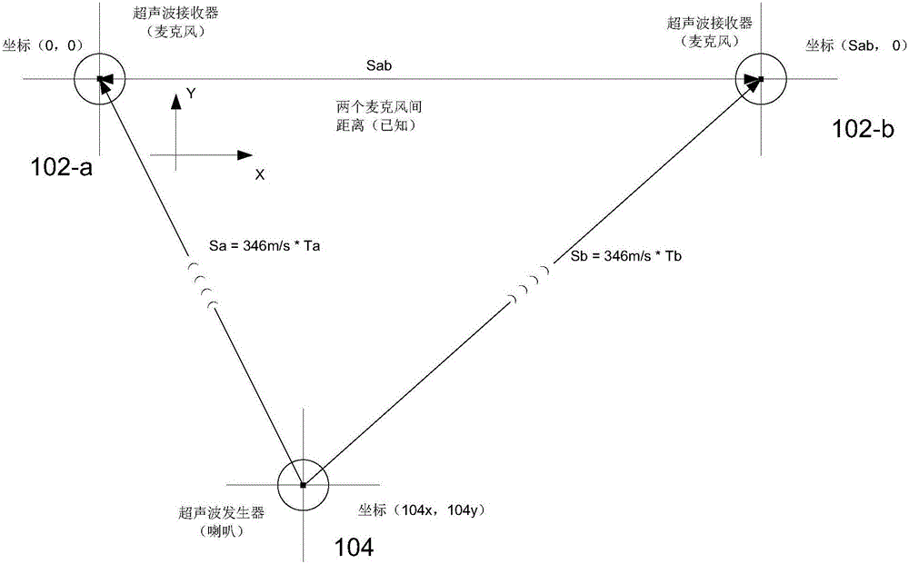
Figure 2 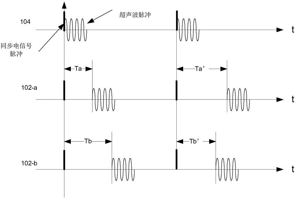
Figure 3
Abstract
Description
Technical field
[0001] The invention belongs to the field of electronic information technology, and relates to a displacement change monitoring system, in particular to a spatial relative displacement change monitoring system. Background technique
[0002] With the rapid development of science and technology, the types of electronic products are becoming more abundant. The control method of electronic products is usually controlled by remote control.
[0003] In recent years, virtual reality and motion sensing technologies have appeared in some game equipment; existing control methods usually use machine vision for posture and displacement detection; such methods are widely used in virtual reality, but there are many disadvantages, such as The machine vision solution using 3D camera and structured light has high hardware cost and high power consumption. It has requirements for the light of the use occasion, the size of the venue, whether there is obstruction, and the detection dis...
Examples
Embodiment 1
[0072] See figure 1 , The present invention discloses a spatial relative displacement change monitoring system, which includes: a first electric pulse mechanism and a first ultrasonic mechanism arranged in the first device 103, and a second electric pulse mechanism arranged in the second device 101 At least three second ultrasonic mechanisms with non-collinear centers, a timing control module, a distance calculation module, a real-time position determination module, and a rotation angle acquisition module; wherein the first device or / and the second device are mobile devices. The timing control module is used to control the timing relationship between electrical pulse signals and ultrasonic signals. The timing control module and the rotation angle acquisition module may be provided in the first device. Of course, the second device may also be provided with the timing control module and the rotation angle acquisition module.
[0073] In this embodiment, the second electric pulse me...
Embodiment 2
[0113] The difference between this embodiment and the first embodiment is that in this embodiment, the first electric pulse mechanism is an electric pulse generator, the second electric pulse mechanism is an electric pulse receiver; the first ultrasonic mechanism is an ultrasonic generator , The second ultrasonic mechanism is an ultrasonic receiver.
Embodiment 3
[0115] The difference between this embodiment and the first embodiment is that in this embodiment, the first device can be a TV, and the second device can be a remote control device (the first device does not move, the second device moves; the receiving end does not move, the sending end moves ); The first device can also be a remote control device, and the second device is a television (the first device moves, but the second device does not move; the receiving end moves, but the sending end does not move).