
The internal support method of the automatic welding internal support device for the circular seam of the tank barrel section
A technology for automatic welding and barrel sections, which is applied in the direction of auxiliary devices, welding equipment, auxiliary welding equipment, etc., and can solve the problems of lack of available internal support devices, etc.
Patent Information
- Authority / Receiving Office
- CN · China
- Patent Type
- Patents(China)
- Current Assignee / Owner
- Publication Date
- 2020-07-07
Smart Images
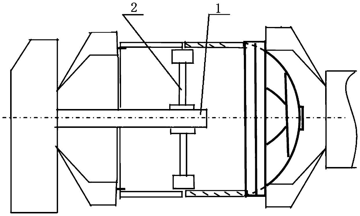
Figure 1 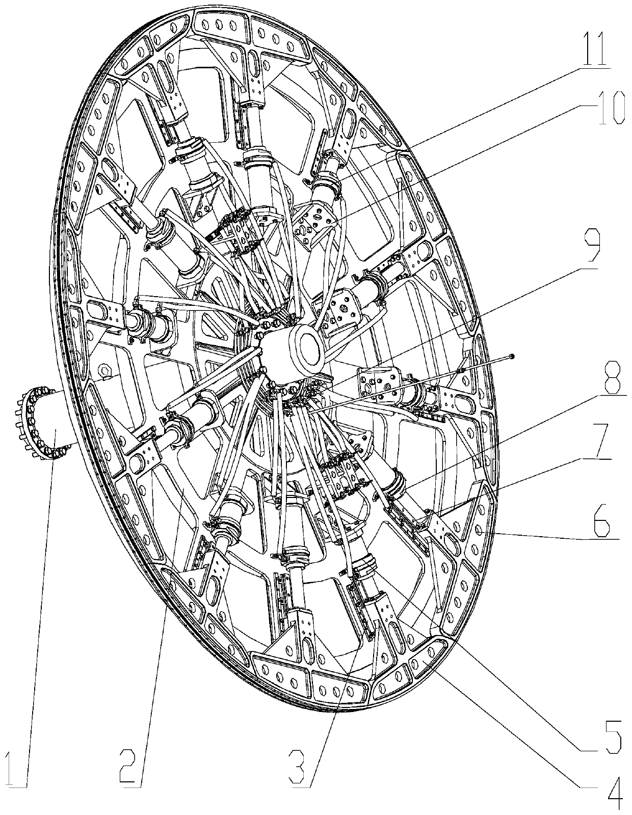
Figure 2 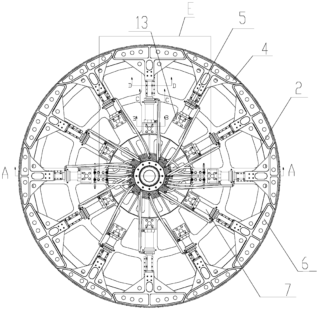
Figure 3
Abstract
Description
technical field
[0001] The invention relates to an inner support device, in particular to an inner support device for automatic welding of the circular seam of the barrel section of a storage tank. Background technique
[0002] The storage tank is a box body assembled and welded by several barrel sections and two box bottoms. The traditional manual welding production mode has been unable to meet the demand due to high labor intensity and low production efficiency. Therefore, the factory has launched an automatic storage tank Welding process research. In order to ensure the smooth progress of the tank automatic welding process test and subsequent product production tasks, the factory purchased the tank girth automatic welding equipment developed by a domestic manufacturer.
[0003] During the automatic welding process of the girth seam of the storage tank section, because the product welding seam is far away from the clamping end face of the equipment, objectively there is a...
Examples
Embodiment 1
[0033] Example 1: see Figure 1 to Figure 15 ,in, figure 1 It is a structural schematic diagram of the present invention when it is used, and it is used for automatic welding of the girth seam of the barrel section of the storage tank.
[0034] An automatic welding internal support device for the circular seam of the tank barrel section, including a vertically arranged main shaft, and a horizontal faceplate 2, the middle part of the faceplate 2 is fixedly connected to the main shaft through a bushing 13,
[0035] The upper surface of the faceplate 2 is provided with several long linear guide rails 7 and several short linear guide rails 3 along its radial direction, and the long linear guide rails 7 and short linear guide rails 3 are staggered and evenly distributed.
[0036] The long linear guide rail 7 is connected to an inner arc-shaped support block 6 through a slider, the end of the inner arc-shaped support block 6 away from the main shaft is an arc-shaped surface, the bo...