
Mechanical equipment accessory
A technology for mechanical equipment and accessories, applied in the field of mechanical equipment accessories design, to achieve the effects of convenient operation, slip prevention and simple structure
Patent Information
- Authority / Receiving Office
- CN · China
- Patent Type
- Applications(China)
- Current Assignee / Owner
- Publication Date
- 2018-06-12
- Estimated Expiration
- Not applicable · inactive patent
Smart Images
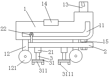
Figure 1
Abstract
Description
technical field
[0001] The invention relates to the technical field of mechanical equipment accessories design, in particular to a mechanical equipment accessory. Background technique
[0002] There are many kinds of mechanical equipment. When the mechanical equipment is running, some of its parts and even itself can perform different forms of mechanical movement. Mechanical equipment consists of driving device, transmission device, transmission device, working device, braking device, protection device, lubrication system, cooling system and other parts. However, the existing special auxiliary accessories for coal preparation lack a device that helps the screw to lift, and there are special auxiliary accessories for coal preparation that not only help to increase the wear resistance of the support plate but also help to prevent the wear plate from slipping. Devices cannot meet people's needs. Contents of the invention
[0003] The object of the present invention is to pr...
Examples
Embodiment Construction
[0013] In order to make the object, technical solution and advantages of the present invention clearer, the present invention will be further described in detail below in conjunction with the accompanying drawings and embodiments. It should be understood that the specific embodiments described here are only used to explain the present invention, not to limit the present invention.
[0014] see figure 1 , figure 1 It is a structural schematic diagram of the present invention.
[0015] Said a kind of mechanical equipment accessory comprises transport seat 1, and the lower end of described transport seat 1 is provided with L-shaped guide groove 11, and the lower end of described transport seat 1 is provided with moving leg 12, and the lower end of described moving leg 12 is installed with Pulley 121, described pulley 121 has two, and is evenly installed on the lower end of slide plate 2, and guide wheel 22 is installed on the upper end of described slide plate 2, and guide whee...