
Orthogonal magnetic circuit radial magnetic suspension bearing based on symmetric self-lubricating flexible auxiliary bearing structure
A magnetic suspension bearing and auxiliary bearing technology, which is applied to magnetic bearings, bearings, shafts and bearings, etc., can solve the problems of reducing rotor rigidity mode, auxiliary bearing stuck, low damping, etc., to avoid high heat phenomenon, improve control accuracy, Improve the effect of rigid modes
Patent Information
- Authority / Receiving Office
- CN · China
- Current Assignee / Owner
- Publication Date
- 2018-08-10
Smart Images
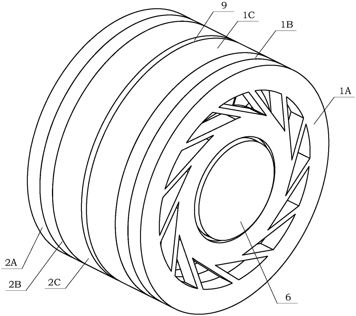
Figure 1 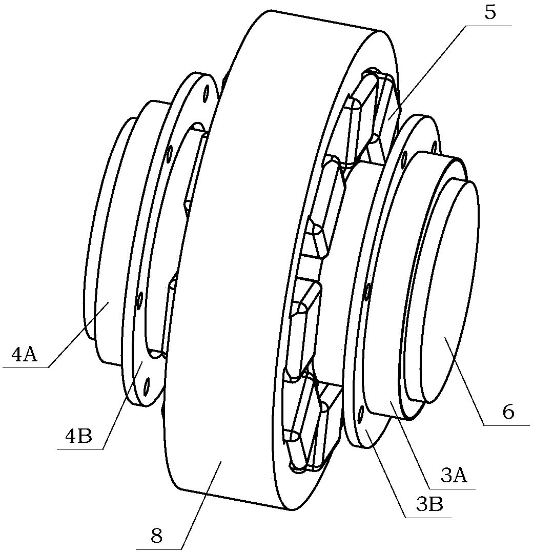
Figure 2 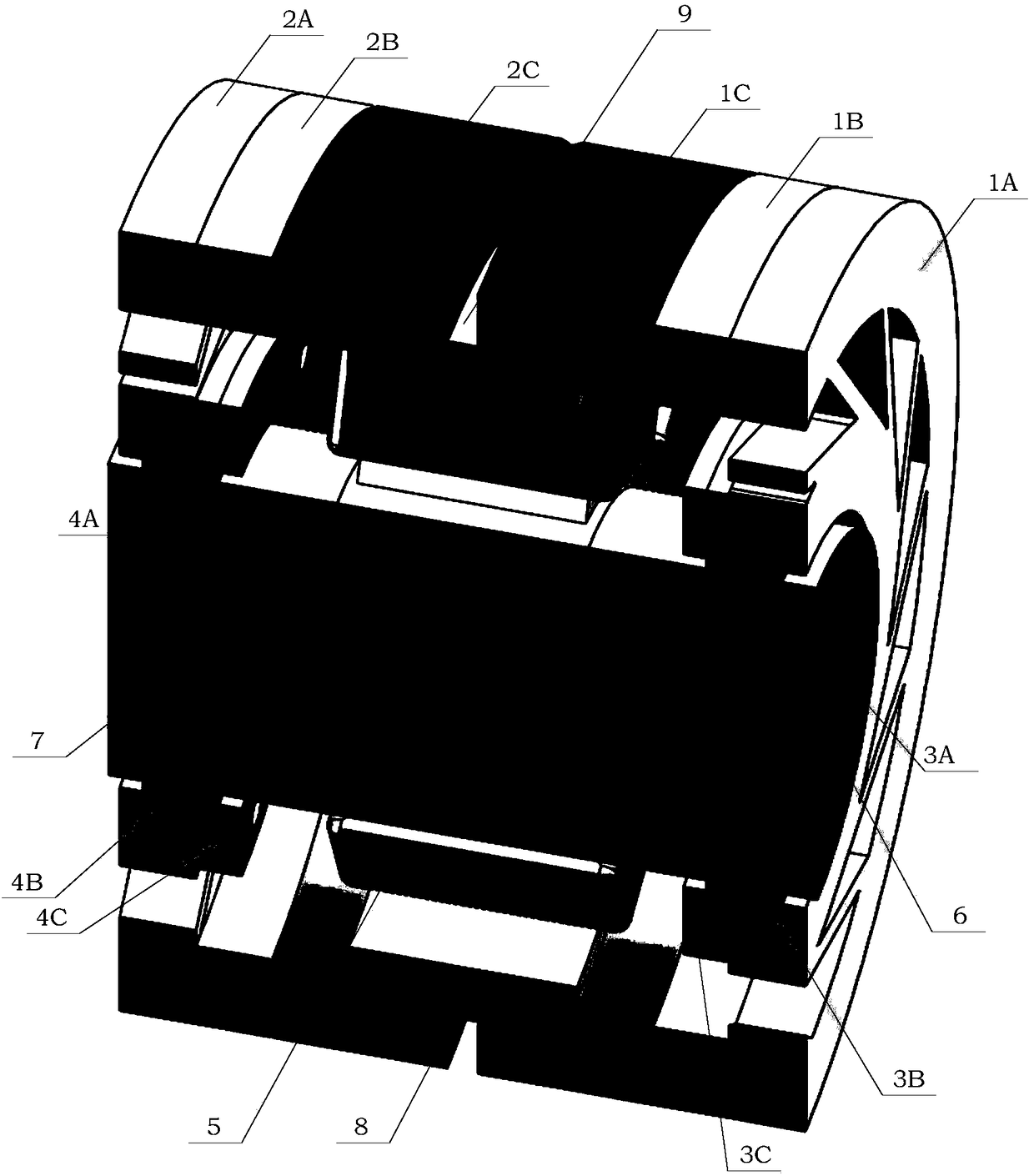
Figure 3
Abstract
Description
technical field
[0001] The present invention relates to a magnetic suspension bearing, more particularly, refers to a magnetic suspension bearing with orthogonal magnetic paths based on a symmetrical self-lubricating flexible auxiliary bearing structure. Background technique
[0002] Magnetic Bearing (Magnetic Bearing) uses magnetic force to suspend the rotor in the air, so that there is no mechanical contact between the rotor and the stator.
[0003] For the structure of the magnetic levitation motor, please refer to "Modeling and Design of 3-DOF Magnetic Bearing for High-Speed Motor Including Eddy-Current Effects and LeakageEffects", author Le Yun, etc., June 2016, Volume 63, Issue 6, published in "IEEE TRANSACTIONS ON INDUSTRIAL ELECTRONICS". of the article figure 1 The overall structure of a typical high-speed magnetic levitation motor is introduced. figure 1 In the left half of , the radial support part of the high-speed magnetic levitation motor is formed by the a...
Examples
Embodiment 1
[0124] see Figure 7 As shown, the orthogonal magnetic path based on the symmetrical self-lubricating flexible auxiliary bearing structure designed by the present invention is applied to the high-speed magnetic levitation motor for performance description.
[0125] Apply the orthogonal magnetic path direction magnetic suspension bearing based on the symmetrical self-lubricating flexible auxiliary bearing structure designed by the present invention to the high-speed magnetic suspension motor, that is, replace the rotor shaft 6 with the output shaft of the motor, through the rotor core 7 and the magnetic bearing stator core The axial position corresponding relationship of 8, the assembled orthogonal magnetic path of the present invention is installed on the motor output shaft to the magnetic suspension bearing, and a radial bearing stop ring 4C on the left end is installed between the magnetic bearing stator core 8 The displacement sensor 20 is equipped with the stator 30 of the...