
Power-assisted manipulator
A technology that assists manipulators and arms. It is applied in the direction of manipulators, program-controlled manipulators, chucks, etc. It can solve the problems of waste of resources and costs, and achieve the effect of increasing or decreasing the movement speed and expanding the scope of use.
Patent Information
- Authority / Receiving Office
- CN · China
- Current Assignee / Owner
- Publication Date
- 2018-08-17
- Estimated Expiration
- Not applicable · inactive patent
Smart Images
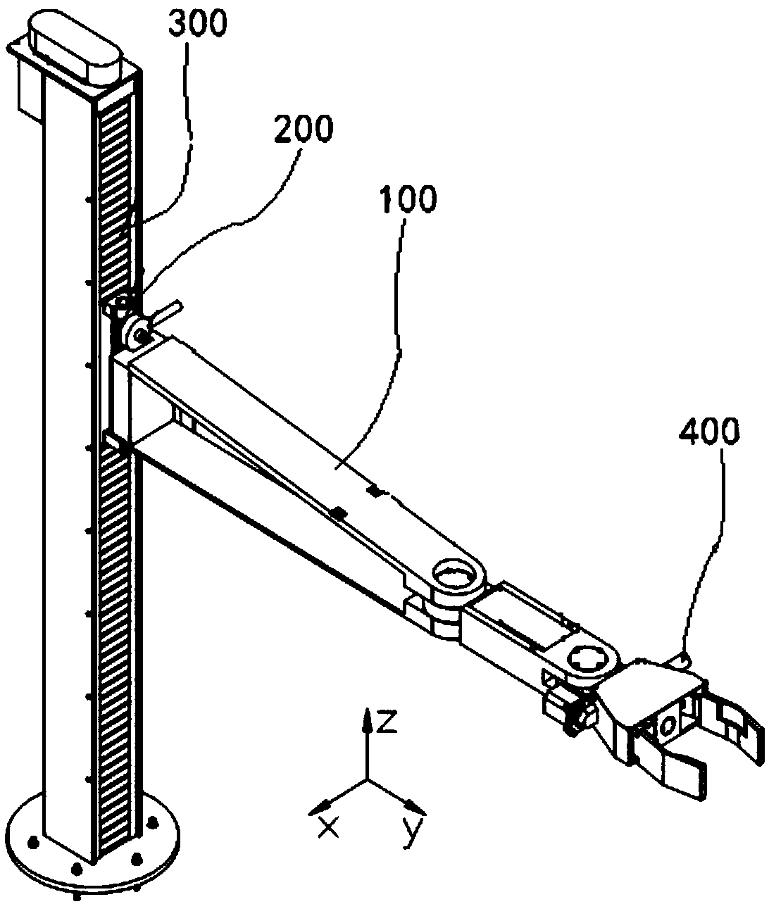
Figure 1 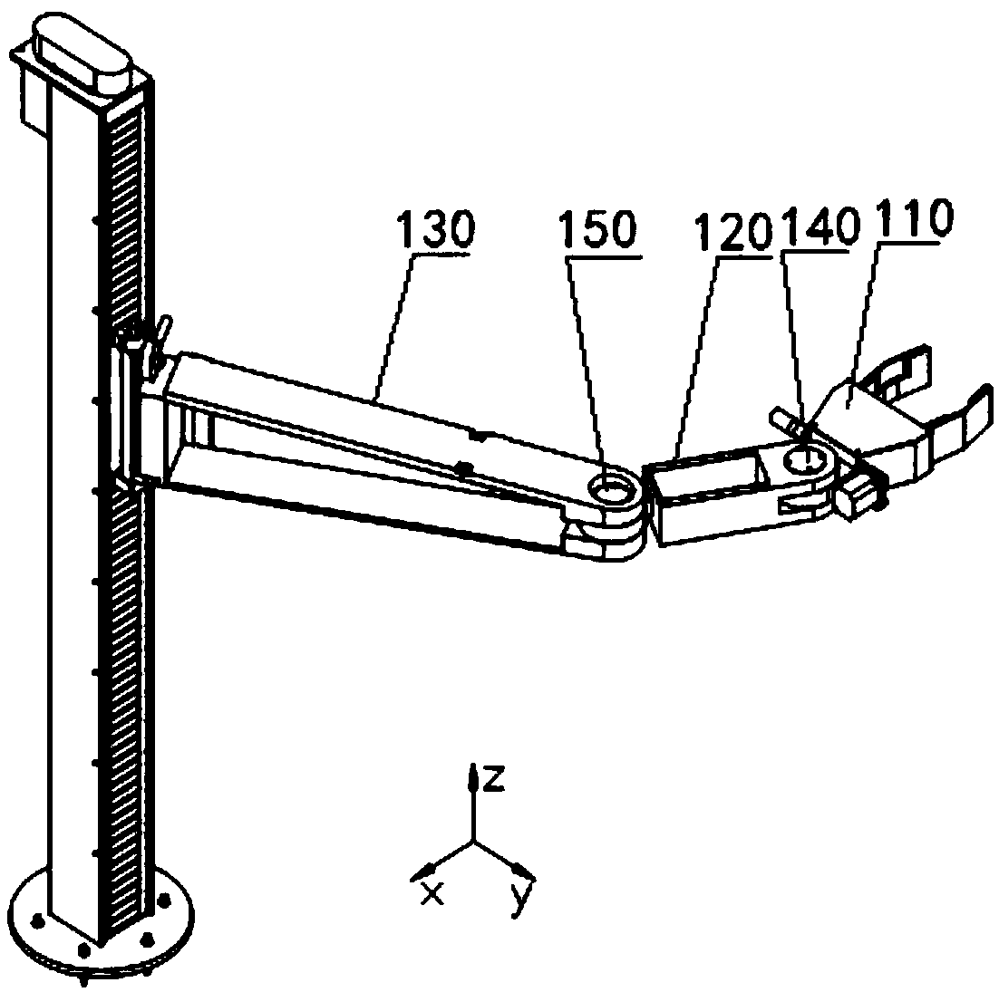
Figure 2 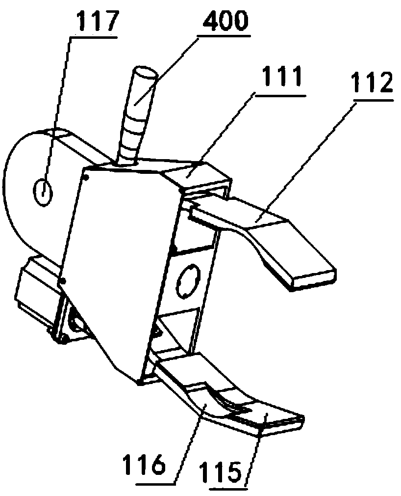
Figure 3
Abstract
Description
technical field
[0001] The invention relates to the field of industrially produced tools in mechanical engineering, in particular to a power-assisted manipulator. Background technique
[0002] In the traditional way of handling, if you encounter a workpiece that is difficult to move, several people are required to carry it at the same time. If the distance is relatively long, it will take a long time. These things will bring a certain amount of waste of manpower and material resources to us, and will eventually increase the cost even more. Manipulators have been widely used as handling tools in industrial production. Most manipulators are special-purpose tools, which are basically only working devices for one or several functions, and they work according to a fixed program. Most of the general-purpose manipulators are fairly intelligent devices, which generally require relatively high-level intelligent software and control systems to work, and their disadvantages are high ...
Examples
Embodiment Construction
[0069] The present invention will be described in further detail below in conjunction with the accompanying drawings and embodiments.
[0070] figure 1 , 17 and 18 show a kind of power-assisted manipulator, which is located in the X-Y-Z three-dimensional coordinate system (Z represents the direction of gravity, and the XY plane simulates a horizontal plane), including an arm 100, a kinematic connection mechanism 200, a lifting drive mechanism 300, a force-sensing handle 400 and a control system, The motion connection mechanism 200 is respectively connected to the arm 100 and the lifting drive mechanism 300. The lifting drive mechanism 300 drives the arm 100 to move up and down along Z through the motion connection mechanism 200. The sensing handle 400 is fixed on the arm 100. When the handle 410 is applied When an upward force is exerted, the arm 100 automatically moves upwards, and vice versa, it moves downwards, thereby achieving the effect of overcoming the effect of gravi...